- Pipe
- Bridges & Structures
- Walls
- Stormwater Management
- Erosion Control
- Start a Project
- Knowledge Center
- Technical Documents
By Bryan N. Scholl, Christopher I. Thornton PhD, P.E., and Barrie King EIT
Published: August 2010
Sediment transport in streams and rivers is inevitable as the stream or river transport capacity rises and falls with the streamflow. If the transport capacity in a location exceeds the sediment supply, erosion will occur. Streambank erosion must be controlled in critical areas (e.g. near bridge crossings) for safety as well as economic reasons. The same is true of bridge piers where general and local scour during a flood event may temporarily or permanently lower the streambed level by several feet, potentially endangering the structure. Articulated concrete block systems (ACBs) are an effective countermeasure if properly designed and installed. This article will cover ACB design including the safety factor analysis and overturning moment design approach outlined in Hydraulic Engineering Circular No. 23: Bridge Scour and Stream Instability Countermeasures: Experience, Selection, and Design Guidance-Third Edition, Volume 2 (HEC-23).
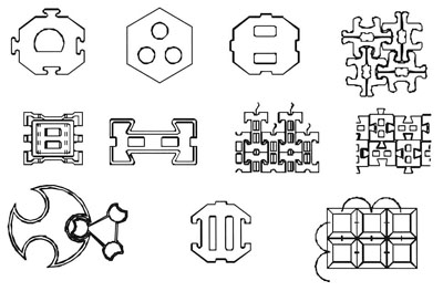
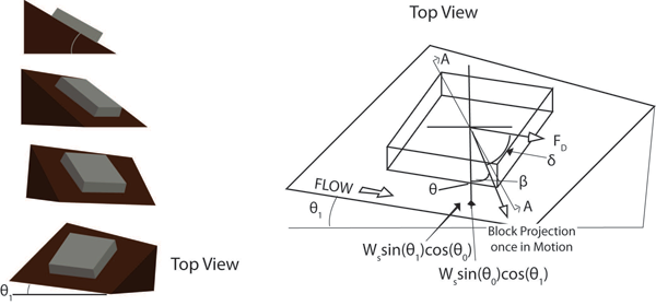
ACBs provide a flexible option to other erosion countermeasures such as riprap, soil cement, grout-filled mattresses, etc. As they are not intended for slope stabilization, slope stability must be ascertained prior to considering an ACB system. ACB systems are composed of preformed concrete blocks that are interconnected through a combination of form and/or cables. The blocks are able to "articulate" to some degree along their adjoining faces, allowing the system to conform to changes in the subgrade while maintaining the protective cover. Open-cell forms of ACB are also available that allow vegetation to be established, improving stability and aesthetic appeal. A few generic examples of potential ACB shapes are presented in Figure 1.
Regardless of the manufacturer specifics, failure of an ACB system is always defined as "the local loss of intimate contact between the revetment and the subgrade it protects." Extensive testing and field monitoring has shown loss of contact can result in one or more of the following:
The importance of maintaining intimate contact with the subgrade cannot be overstated, and a suitable filter and/or drainage layer are considered essential to the proper design of an ACB system. A detailed discussion of filter design is beyond the scope of this article but may be found in Design Guide 16 of HEC-23. If dune-type bedforms may occur at the protected slope's toe, it is strongly recommended that only a geotextile filter be considered. When evaluating a potential ACB system for which performance testing utilized a drainage layer, a drainage layer must also be used in the design.
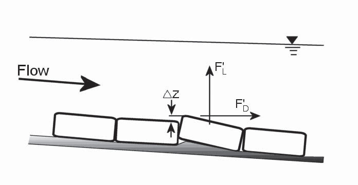
ACB system design uses a discrete particle approach similar to that introduced by Stevens and Simons (1971) and modified by Julien (1995) in the "Factor of Safety" derivation method for sizing riprap. For ACBs, the force balance has been recomputed using the weight and geometry of the concrete blocks and test results are used in place of the Shield's relationship. Also, additional lift and drag forces generated by block protrusion above the surrounding matrix level are considered. Figure 2 presents additional lift and drag forces created by block protrusion, F'L and F'D respectively.
The recommended design procedure for ACBs is the "factor of safety" method. Step 1 is to determine the minimum acceptable target factor of safety from site-specific details using Tables 1 through 3 and the relationship:
Equation 1:![]()
where:
SFT = target factor of safety,
SFB = base factor of safety,
XC = multiplier based on consequence of failure, and
XM = multiplier based on hydraulic model uncertainty.
According to HEC-23, "typically, a minimum allowable factor of safety of 1.2 is used for revetment (bank protection) when the project hydraulic conditions are well known and the installation can be conducted under well-controlled conditions. Higher factors of safety are typically used for protection at bridge piers, abutments, and at channel bends due to the complexity in computing hydraulic conditions at these locations." The proposed design is then evaluated using a moment balance approach to follow. The factor of safety is then iteratively evaluated against the minimum acceptable value until an acceptable design is determined.
| Example Application | SFB |
| Channel bed or bank | 1.2 – 1.4 |
| Bridge pier or abutment | 1.5 – 1.7 |
| Overtopping spillway | 1.8 – 2.0 |
| Consequence of failure | XC |
| Low | 1.0 – 1.2 |
| Medium | 1.3 – 1.5 |
| High | 1.6 – 1.8 |
| Extreme or loss of life | 1.9 – 2 .0 |
| Hydraulic model | XM |
| Deterministic (e.g. HEC-RAS, RMA-2V) |
1.0 – 1.3 |
| Empirical or stochastic (e.g. Manning's or Rational Equation) |
1.4 – 1.7 |
| Estimates | 1.8 – 2.0 |
Once the target factor of safety has been determined (Step 1), design steps are as follows: 2) calculate design shear stress, 3) obtain ACB properties, 4) calculate the factor of safety parameters for each product, and 5) calculate the factor of safety for potential blocks and choose the appropriate product based on the target factor of safety. Design shear stress tdes is calculated using Equation 2:
Equation 2:![]()
where:
tdes = design shear stress (lb/ft2),
Kb = bend coefficient(dimensionless),
? = unit weight of water (lb/ft3),
y = maximum depth of flow on revetment(ft),
Sf = slope of the energy grade line(ft/ft).
Equation 3: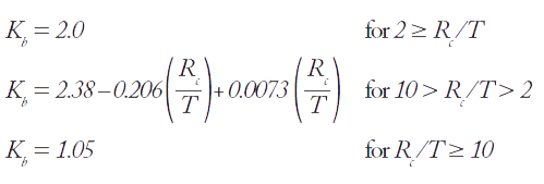
The bend coefficient is used to calculate the
increased shear stress on the outside of a bend.
Kb is a function of the ratio of the radius of
curvature Rc and the top width of the channel T
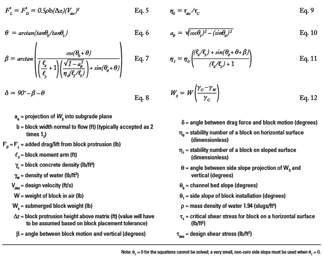
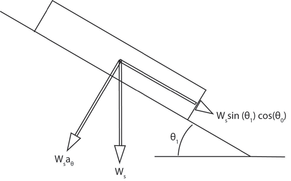
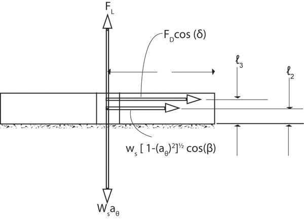
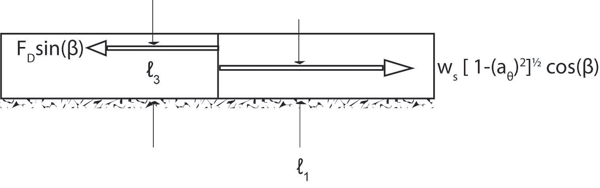
Figures 3 through 6 present schematics of a single ACB on a side slope with variables defined for the factor of safety analysis. Required block properties that must be obtained are presented in Figure 5 and Figure 6. In the general case, the pivot point 'O' will be located at the downstream, downslope corner of the block.
The safety factor SF of a single block in the ACB matrix that must be evaluated against the previously calculated target factor of safety SFT is the ratio of restraining moments to overturning moments,
Equation 4: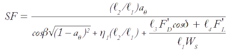
Variable definitions and calculation methods are presented in Table 4. These equations may be used with English or SI units provided consistency is maintained.
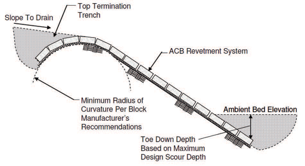
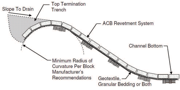
Once a block has been selected, the longitudinal and vertical extent of the installation must be determined. Longitudinally, "revetment armor should be continuous for a distance which extends both upstream and downstream of the region which experiences hydraulic forces severe enough to cause dislodging and/or transport of bed or bank material. The minimum distances recommended are an upstream distance of 1.0 channel width and a downstream distance of 1.5 channel widths. ... In meandering reaches, …the present limit of erosion may not necessarily define the ultimate downstream limit. FHWA's Hydraulic Engineering Circular No. 20, Stream Stability at Highway Structures, provides guidance for the assessment of lateral migration."
Vertically, freeboard above the design water surface must be provided. If the reach is unconstricted, a minimum freeboard is 1 to 2 feet; if constricted, the minimum is 2 to 3 feet. For supercritical flow, freeboard is measured from the energy grade line, not the water surface. The system must cover the entire channel bottom. Or, if the channel bed is unlined, it must extend below the bed level to the extent that it will not be undermined by maximum scour caused by toe scour, contraction scour, and long-term degradation in combination. The recommended extent of vertical installation is presented in Figures 7 and 8.
Safety factor calculation methods are similar for revetment or pier scour applications with two notable exceptions: design velocity Vdes and design shear stress tdes determination. For typical revetment applications, a cross sectional average velocity is generally acceptable if a detailed hydraulic analysis has not been performed. Flow conditions near bridge piers are more severe; however, and require that local velocity and shear stress values be determined. If a stream velocity distribution is unavailable, the recommended method is provided in NCHRP Report 593:
Equation 13![]()
where:
Vdes = design velocity for conditions at the pier (ft/s),
K1 = pier shape factor equaling 1.5 for round-nose piers and 1.7 for square-edge piers,
K2 = velocity adjustment factor for pier location in the channel ranging from 0.9 near the bank in a straight reach to 1.7 when the pier is located in the main current of flow around a sharp bend,
Vavg = average approach velocity upstream of the bridge (ft/s).
If the velocity distribution is available, the maximum velocity in the active channel Vmax should be used
Equation 14![]()
The design shear stress at the pier is then calculated using,
Equation 15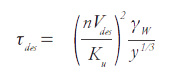
where:
tdes = design shear stress for local pier conditions(lb/ft2),
n = Manning's "n" value for the block system,
Vdes = design velocity determined by Equation 13 or 14 (ft/s),
?w = unit weight of water (62.4 lb/ft3 for fresh water),
y = depth of flow at pier (ft), and Ku = 1.486 for English units, 1.0 for SI.
It has been shown that optimum performance of ACBs in pier scour protection is obtained when the blocks are extended at least twice the pier width in all directions from the pier. Recommended pier installation is presented in Figure 9. If only local scour is expected, the system may be installed horizontally, flush with the streambed providing turndowns at the periphery. If other processes or types of scour are expected, the system must be sloped away from the pier in all directions, terminating at the periphery below the streambed at a depth greater than the maximum expected scour or bedform troughs, whichever is greater. Blocks should not be placed on a slope greater than 2H:1V (50 percent), even if this results in blocks being placed greater than two pier widths from the pier.
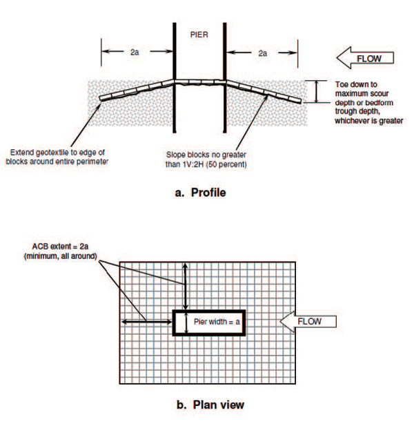
Assistance in predicting bedform geometry may be found in Karim (1999), van Rijn (1984), and Bennett (1997), who provided an upper limit of crest-to-trough height, ?, as ? < 0.4y where y is the depth of flow. This would suggest the maximum bedform trough depth below ambient level is approximately 0.2 times the depth of flow.
Wall piers or pile bents consisting of multiple columns may be skewed to the direction of flow and the ACB protection must be extended to protect against the additional scour potential. In the absence of definitive guidance, the system should be extended by a factor Ka a function of pier width (a), length (L) and skew angle (a),
Equation 16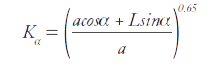
A filter is typically required for bridge pier applications of ACBs and should extend beneath the complete extent of the system. "The geotextile should be securely attached to the bottom of the pre-assembled ACB mat prior to lifting with a crane and spreader bar. In shallow water where velocities are low, the geotextile may be placed under water and held in place temporarily with weights until the blocks are placed." As in the case of revetment installations, if dune-type bedforms may be present, it is strongly recommended that only a geotextile filter be considered. An observed failure point at ACB bridge pier installations is the seal where the mat meets the pier. Securing the geotextile to the pier aids in preventing bed material loss around the pier. Structural attachment of the mat to the pier is strongly discouraged; moment transfer from the mat to the pier may affect the structural stability of the pier.
When properly designed, an ACB system can provide an excellent design alternative when considering the level of protection afforded for the installed cost.
Bryan N. Scholl, is a research assistant for Colorado State University.
Christopher I. Thornton, Ph.D., P.E., is director of the Hydraulics Laboratory and Engineering Research Center at Colorado State University.
Barrie King, E.I.T., is the supervisor of engineering for CONTECH Construction Product's Armortec product line.
Online quiz for this article is not active and
PDH credit is no longer available.
This article is being maintained for informational purposes only.