- Pipe
- Bridges & Structures
- Walls
- Stormwater Management
- Erosion Control
- Start a Project
- Knowledge Center
- Technical Documents
By Darrell Sanders, P.E. and Andrew Jenkins
Published: December 2010
Buried flexible structures used for culverts, drainage, and sewers are fabricated from a variety of materials to form soil-interaction pipe systems. The physical properties of each material or combination of materials used to fabricate pipe are characterized by either linear or non-linear elastic behavior that is strongly influenced by strain rate. This paper discusses the basic material properties that affect strength, the technical differences between the terms flexibility factor and pipe stiffness, the practical implementation of flexibility and stiffness values that are associated with various pipe products, and how these affect handling, installation, and short-term and long-term performance.
When the AASHTO LRFD Bridge Design Specifications Section 12 were written, all buried structures were grouped together in a common document. This is convenient for the designer who is charged with evaluating and specifying buried pipe and conduit that is used for culverts, drainage, and sewers. This article focuses on flexible pipe structures.
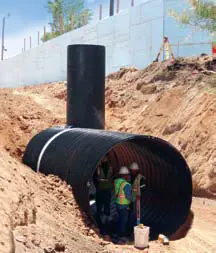
Ninety-six-inch steel-reinforced polyethylene pipe installation in New Mexico
Considering engineering mechanics of solids, there are two general classes of material used to fabricate flexible pipe. Materials that are classified as linear elastic include steel (AASHTO M36, M245) and aluminum (AASHTO M196) pipe of various corrugation depths and steelreinforced thermoplastic pipe (AASHTO MP20-10). Materials that are classified as non-linear include corrugated, solidwall and profile-wall high-density polyethylene or HDPE (AASHTO M294, and ASTM F714-08, respectively), profilewall and solid-wall polyvinyl chloride or PVC (AASHTO M304 and AASHTO M278) and glass-reinforced polymer mortar (ASTM D3262 and D3754). Table 1 lists these flexible pipe types and compares properties.
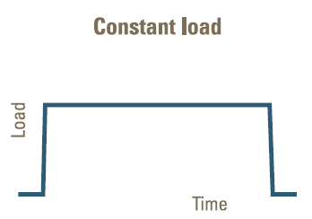
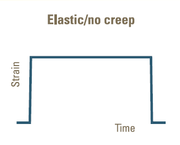
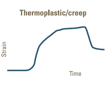
As a linear elastic material, metals behave predictably within typical service temperatures and maintain their mechanical properties under constant load (Figures 1 and 2). Thermoplastic materials exhibit non-linear elastic behavior and are sensitive to rate of strain, temperature, and creep. Creep is a visco-elastic phenomenon where the strain in a material continues to increase with time when subjected to a constant load (Figure 3). Although glass fibers show linear elastic behavior in a small displacement field (small strain), they do, along with most polymers used to fabricate plastic pipe, behave with visco-elastic characteristics and exhibit creep under long-term loads.
The industry recognizes the difference between short-term and longterm plastic pipe properties and sets elastic modulus properties accordingly. Depending on the chemistry of the thermoplastic material, the ratio of short-term to long-term elastic modulus ranges between 3 and 5.
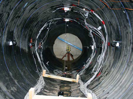
Strain gage placement per steel-reinforced polyethylene pipe full-scale load testing
All flexible pipes are designed for strength using the same general approach. For a given material, wall section, and pipe diameter: the applied loads are determined, soil-interaction with the flexible pipe is modeled, stress in the wall area is computed, then local effects such as buckling or seam strength are checked.
Linear elastic materials are addressed in AASHTO LRFD Section 12.7 and non-linear plastic materials are addressed in AASHTO LRFD Section 12.12. Readers will notice that while the two specification sections use the same general approach to overall design, the physical differences in the character of the materials are treated with appropriate elastic or thermoplastic consideration. The engineer must use judgment to select appropriate short or long term modulus values. These values are necessary for limit state computations.
Inconsistencies between descriptive language and the equations within the AASHTO specification can be difficult for the engineer to interpret.
| Primary Structural Material | Elastic Behavior | Creep Behavior | Temperature-Dependent Behavior | Short-Term Elastic Modulus (ksi) | Long-Term Elastic Modulus (ksi) |
| Corrugated Steel- ¼ inch & ½ inch deep |
Linear | No | No | 29,000 | 29,000 |
| Corrugated Steel-1 inch deep | Linear | No | No | 29,000 | 29,000 |
| Spiral Ribbed Steel | Linear | No | No | 29,000 | 29,000 |
| Steel Structural Plate | Linear | No | No | 29,000 | 29,000 |
| Steel-Reinforced Polyethylene | Linear | No | No | 29,000 | 29,000 |
| Corrugated Aluminum- ¼ inch & ½ inch deep |
Linear | No | No | 10,000 | 10,000 |
| Corrugated Aluminum-1 inch deep | Linear | No | No | 10,000 | 10,000 |
| Spiral Ribbed Aluminum | Linear | No | No | 10,000 | 10,000 |
| Aluminum Structural Plate | Linear | No | No | 10,000 | 10,000 |
| Glass-Reinforced Polymer Mortar* | Non-Linear | Yes | Yes | 2,600 | 1,500 |
| Profile Wall PVC | Non-Linear | Yes | Yes | 440 | 140-158.4 |
| Solid Wall PVC | Non-Linear | Yes | Yes | 440 | 140-158.4 |
| Solid Wall HDPE | Non-Linear | Yes | Yes | 110 | 22 |
| Corrugated HDPE | Non-Linear | Yes | Yes | 110 | 22 |
| * GRPM pipe elastic modulus are apparent values based on hoop testing. | |||||
Serviceability is considered for all flexible pipe materials. The overall idea is that a flexible, round pipe should stay (essentially) round during fabrication, handling, delivery, installation, backfilling operations, and initial soil consolidation. All of the soil-interaction models are based on the assurance that a round pipe maintains the desired shape. Also, all joint types, including soil-tight, silt-tight, leak-resistant, and special designs (designed to resist shear, bending, pull apart, pressure, or water-tight), are dependent on the anticipated roundness of the pipe (AASHTO PP63-09). Because construction is not a perfect science, some allowances are made recognizing that flexible round shapes won't be perfect in geometry, but will still function as desired while being structurally sound.
The approach to checking the handling and installation stiffness (or how well the pipe is expected to maintain a round shape) for most flexible pipe systems is based on the concept of the flexibility factor or FF which is computed by the equation:
Equation 1
FF = D2/EI (inches/kip)
where:
D = Diameter in inches (in.);
E = Est = Short Term Modulus (ksi);
and
I = Moment of Inertia of the Pipe Wall (in.4/in.)
The computed flexibility factor should not exceed the limits prescribed by AASHTO Section 12. Note that the short-term modulus for plastic pipe does not account for any temperature effects during stockpiling or storage immediately prior to installation.
ASTM D2412 is known as the parallel plate test and is used to measure the load at which a predetermined deflection is observed in a particular sample of plastic pipe. The parallel plate test is governed by ASTM sub-committee 17.11, which has responsibility for developing and maintaining standards for plastic pipe. In the test method, the term pipe stiffness is used to quantify laboratory behavior that is somewhat unique to thermoplastic pipe and reinforced polymer mortar pipe.
The test method recognizes possible variability in measured data because of the intrinsic properties of thermoplastic pipe materials. As a result, the rate of deflection and testing temperatures are specified in exact terms. One purpose of carefully controlled test conditions is to establish a precision statement for the test method. Precision statements are mandatory for all ASTM Test Methods per the ASTM manual on "Form and Style for ASTM Standards (March 2010)."
The Form and Style manual states: "Precision is the closeness of agreement between test results obtained under prescribed conditions. A statement on precision allows potential users of the test method to assess in general terms its usefulness in proposed applications. A statement on precision is not intended to contain values that can be duplicated in every user's laboratory. Instead, the statement provides guidelines as to the kind of variability that can be expected between test results when the test method is used in one or more reasonably competent laboratories."
The results from the practical application of the test method help a manufacturer with quality control for a product as various day-to-day production variables must be addressed. Certificates ensuring the purchaser that a quality control program is utilized should accompany the materials during delivery. As part of an overall quality control plan, a manufacturer can use the test method to:
Equation 2
PS = F/?y (lbf/in./in.)
where:
F = Force per inch of Pipe Length (lbf/in.)
?y = Deflection at F (in.)
The test method warns, "although PS units are dimensionally the same as those for pressure and stress, they are different quantities and should not be confused one with the other."
As a result, pipe stiffness as determined by ASTM D2412 is not the same as the pipe stiffness value used in AASHTO Section 12.12. Simply stated, this is not a direct comparison. The prescribed deflection rate and temperature of the ASTM parallel plate test are not relevant to actual in situ loads and exposure temperatures of a buried pipe.
For a composite pipe system such as steel-reinforced polyethylene, the use of pipe stiffness per ASTM D2412 is intended to provide a basis for manufacturing quality control not structural design. AASHTO MP20-10 states, "The pipe shall have minimum pipe stiffness at 5 percent deflection as listed [in the tables]… 5 percent deflection criteria was selected for testing convenience and should not be considered as a limitation with respect to in-use deflection."
Equations in AASHTO Section 12.12 contain terms that appear to be similar to pipe stiffness. These computed terms are different than the numbers that result from tested pipe stiffness. For example, strain is computed for thermoplastic pipe per AASHTO Section 12.12.3.5.4 using a series of equations that consider pipe stiffness. Throughout the computations, the long-term modulus value is used. In this procedure, the equation for pipe stiffness is:
Equation 3
PS = F/? = EltI/(0.149 R(sup)3) (kip/in.-in.)
where:
F = Load per inch of Pipe (kip/in.)
? = Vertical Deflection of Pipe (in.)
Elt = Long Term Modulus (ksi)
I = Moment of Inertia of the Pipe Wall (in.4/in.)
R = Radius of Pipe to Centroid of Wall Section (in.)
Unlike Equation 3, it is important to emphasize that in the procedure described by ASTM D2412, the magnitude of pipe stiffness is determined by a carefully controlled laboratory test. Traditionally, pipe stiffness is not used for corrugated metal pipe; however, it does have usefulness with steel-reinforced polyethylene pipe. Although dimensionally the same as stress, pipe stiffness does not compute a magnitude of stress in the pipe wall.
Where quality control is procedural and testing protocol establishes a basis for acceptance, quality assurance is practice based and related to documenting or providing a pledge of performance. In a manufacturing setting, quality assurance takes the form of providing a certificate or some other tangible means that the product was manufactured, tested, and supplied in accordance with a predetermined specification. The pipe stiffness values, as measured by the parallel plate test in ASTM D2412, provide data relevant to acceptance of a finished product compared with an established baseline in strictly controlled laboratory testing conditions.
At the jobsite, installation assurance should follow industry standards such as AASHTO LRFD Bridge Construction Specifications. Corrugated metal pipe is addressed in Section 26 and thermoplastic pipe is addressed in Section 30. Both specification sections state that the overall performance of the flexible pipe is highly dependent on installation handling, backfill material, and methods used to place and compact the backfill. Final visual inspection and acceptance of the installation by the owner's technical representative is made significantly easier when appropriate consideration is given to pipe flexibility and pipe stiffness principles. At the time of this article, the principles of either Section 26 or 30 can be used for the installation of steel-reinforced polyethylene pipe.
Many flexible pipe systems are commercially available in a variety of materials, sizes, and wall configurations. In order to understand the overall behavior, design, and installation of flexible pipe, it is important to know how to navigate various industry specifications. Practitioners should be aware that the key difference between the behavior of metal and steel-reinforced polyethylene pipe and the behavior of thermoplastic pipe is how the time-dependent modulus is applied. Appropriate use of flexibility factor and pipe stiffness concepts for serviceability is emphasized.
Pipe stiffness is not necessarily related to the buried pipe's ability to handle loads. Pipe stiffness, as determined by ASTM D2412, is a tested value and it is not used in strength checks in the AASHTO specification. Appreciation of the differences related to types of pipe materials being considered for applications is critical. Misconceptions and misuse of standards should be avoided. With careful consideration and understanding of design principles, the practitioner can evaluate short-term installation considerations along with long-term structural reliability.
Darrell Sanders, P.E., is chief engineer for CONTECH Construction Products Inc. He holds a B.S. degree in Civil Engineering from the University of Cincinnati and an MBA from the University of Dayton. He has been a registered Professional Engineer in Ohio since 1996. Sanders is a member of several industry committees, including NCSPA, AASTHO, ASTM, and Uni-Bell.
Andrew Jenkins, E.I., is the national plastic products manager for CONTECH Construction Products Inc. He holds a B.S. degree in Engineering from Missouri University of Science and Technology (Rolla). Jenkins' experience comes from 13 years in the petroleum, mining, and civil engineering industries.
Online quiz for this article is not active and
PDH credit is no longer available.
This article is being maintained for informational purposes only.