- Pipe
- Bridges & Structures
- Walls
- Stormwater Management
- Erosion Control
- Start a Project
- Knowledge Center
- Technical Documents
By Julia Frazier, P.E. and Rachel Lageman, P.E.
October 2024
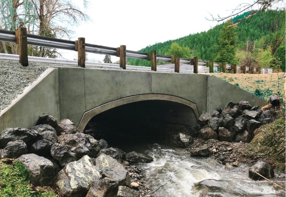
Open-bottom buried bridges are structures built with side walls and a top that’s either flat or in an arc formation. With either configuration, the bottom is not constructed as part of the bridge structure, which provides a foundation design that’s separate from the bridge’s structural design. The structure sides support the surrounding soil, while the open bottom has the flexibility for a variety of site adaptations.
This feature is useful with existing streambed conditions where it’s essential to reduce site disturbance. Where the bridge spans over the streambed, the natural soils can be preserved, assisting in the sustainability of wildlife and fish passage. A buried bridge structure limits the exposed structural elements, reducing maintenance time and costs by protecting the bridge against exposure to de-icing materials. A prefabricated concrete structure is constructed at an offsite precast plant location and delivered to the site, reducing the overall construction time as compared with onsite conventional stick-built-type bridge structures.
Prefabricated, buried bridges can be used in several site intersections. These include—but are not limited to—railway over/under roadway, roadway over roadway, airplane passage over roadway and roadway over streambed. Because the roadway over streambed application is the most common site intersection for buried, three-sided structures, this article describes the conditions related to that type. Many of the site considerations presented in this article can be adapted if a different intersection is under consideration.
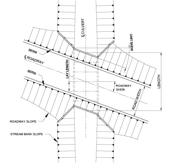
Figures 1 and 2 depict some of the basic terminology used to identify the components of a prefabricated buried bridge structure. As opposed to conventional bridges, the overall length of a buried bridge refers to end measurement along the span’s centerline. The span and rise are used to delineate the size of the structure. The span is measured at the inside face of the structure, perpendicular to the bridge legs.
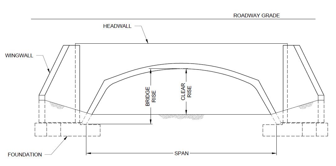
With open-bottom bridge structures, it’s often necessary to differentiate between bridge rise and clear rise. The bridge rise is the dimension from the bottom of the prefabricated structure to the inside structure top measured at the midspan, where the height is the greatest. The clear rise is measured from the underpass or streambed elevation to the underside of the bridge at the midspan. Because the clear rise can vary throughout the length of the bridge, the clear rise often is given at both the upper and lower ends of the structure.
Prefabricated bridges often will be shipped to the site in segments. The length of each bridge segment is called the lay length. The lay lengths may vary based on the weight of each piece, the form lengths or to meet the required overall bridge length. Transportation limitations such as dimensional size and total weight also may require a limitation on the lay lengths. When all the bridge segments are installed, the overall bridge length can be obtained.
There are two potential skew angles that can be specified for the bridge layout. The first is the roadway skew angle, which refers to the angle between the structure and the centerline of the roadway. In situations where the ends of the unit are skewed for aesthetic or structural reasons, a second skew angle will be depicted as the unit skew angle, which is the angle between the fascia of the unit and the end of the structure. The unit skew and roadway skew do not need to be at the same angle.
As the bridge is installed below the ground surface, it’s often necessary to retain the soil above and around the bridge with headwalls and wingwalls. The headwalls are located at the ends of the bridge on top of the end units to retain the soil on top of the bridge structure. The wingwalls are vertical elements that attach to the bridge ends and act as retaining walls for the soil around the bridge structure, while transitioning the grade from the roadway to the streambed. Proper layout of the wingwalls is subsequently discussed in more detail.
The foundation is an essential element to the bridge’s structural stability. With open-bottom structures, the foundation is placed under the entire length of the bridge structure to support the bridge legs and distribute the load to the soil. There are a variety of foundation options that can be used, including strip footing, pedestal footing, deep foundation or base slab design.
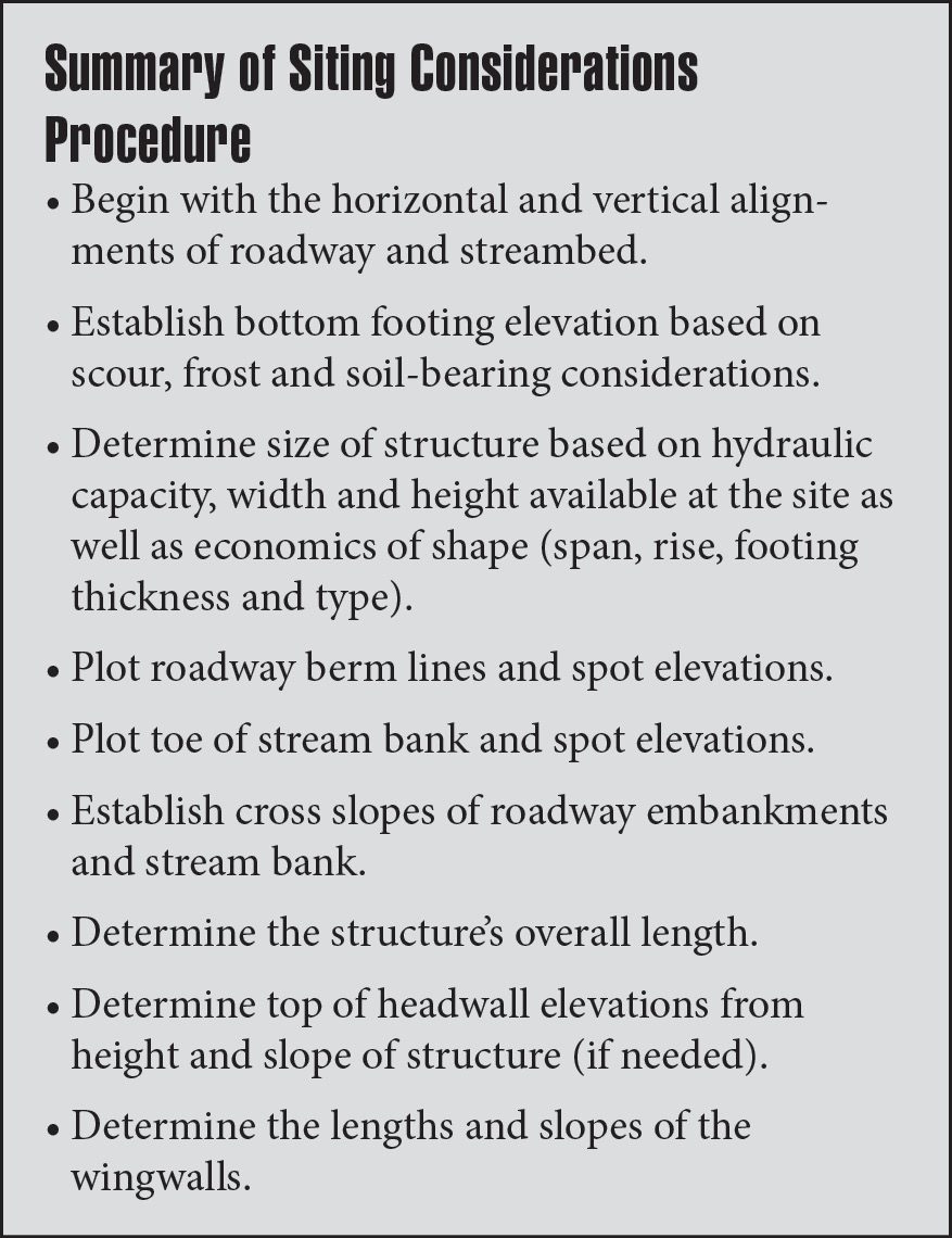
Many siting considerations are common to all bridges, while others are more specific to buried and open-bottom structures. All stream-crossing bridges require the proper location and must meet hydraulic requirements. Other common siting considerations include the following: reviewing the natural terrain to find the most-efficient placement for the structure, identifying the relationship of the roads and intersecting streambeds, determining the size of the bridge necessary for stream hydraulics, and the soil grade above the structure.
Natural site conditions should be considered to determine the bridge’s optimal location. When spanning a waterway, the bridge should match the natural alignment of the streambed in both horizontal angle and vertical grade. The siting also should consider a location that can minimize the bridge’s overall length, which is achieved where the streambed is perpendicular to the road above. However, many times this ideal layout location may not be attainable.
Prior to designing the bridge structure, the following items (discussed later in this article) should be obtained to determine the proper layout of the bridge structure:
• Overall site plan (e.g., roadway and stream alignment, right-of-way information, site features)
• Grading plan
• Soil parameters for backfilling and bearing capacities
• Hydraulic requirements
• Roadway cross sections
The following are additional items needed for buried structures, but will only receive limited discussion because they’re not within the scope of this article:
• Foundation selection
• Bearing capacity
• Scour protection
• Hydraulics
• Environmental factors
The site plan will identify the roadway and stream alignments, right-of-way information, and other site features in the project area. The grading plan will help determine the amount of cover over the structure after the bridge rise has been established.
A geotechnical engineer should perform a geotechnical site investigation. If the geotechnical engineer determines that the soils will likely become unstable with the concentrated water flow beneath the bridge, foundation depths could be lowered to prevent scouring or other scour countermeasures could be implemented. Elevations of any rock formations should be provided and taken into consideration.
The amount of cover—or soil—over the bridge also should be considered when determining the bridge location. As a minimum, the cover should be sufficient to maintain the pavement cross-section over the structure to ensure good pavement performance. Also, underground utilities should be considered if they’re located in the fill over the bridge. With buried bridges, the ability to locate utilities in the backfill over the top of the structure often is advantageous and may have a direct impact on the cover requirements. Contact the manufacturer for the maximum cover limits.

When dealing with structures over waterways, the proper span (width of the opening) and bridge rise (height) will mainly depend on stream hydraulics. For waterway applications, interior bridge dimensions will establish a minimum bridge size to obtain the proper flow-through volume and headwater requirements. However, the principles of hydraulic engineering are outside the scope of this article.
For most waterway applications, the structure must—at a minimum—span the width of the stream channel. The spans over waterways also could be controlled by environmental considerations such as fish passage, maintenance of natural stream morphology, animal migration and adjacent wetlands, all of which could increase the required span. When dealing with bridges for roadway and railway applications, it’s also necessary to take into account proper clearances, including vehicular heights and widths, to determine the minimum span and rise dimensions for the structure. The rise dimension also must take the elevations from the underpass/overpass differences into account.
The bridge can be installed with or without a slope along the length of the bridge. However, slopes should be avoided wherever possible for structures bearing on soil. When slopes cannot be avoided, special considerations must be made depending on the bearing material. Contact the manufacturer for more information.
The degree of slope is based on the upper and lower end elevations. For hydraulic reasons, it’s often desired to have a constant flow-through area throughout the length of the bridge. If there is a considerable difference in grade between the upstream and downstream ends, a slope may be required to provide this constant opening size. However, because the bridge system is open-bottom, it’s also permissible to install the bridge flat and establish the slope in the streambed to match existing grades. This application is optimal where the upper and lower end elevations can provide adequate flow-through open area at both upstream and downstream clear rises.
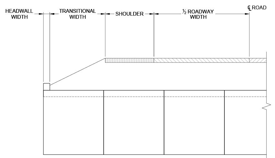
The length of the bridge will be primarily determined by the road’s cross-section, including berm and sidewalks (if applicable). Determining the length of the bridge should begin by adding up the following items (see Figure 3):
• Roadway cross-sectional width
• Required berm/shoulder width
• Headwall width
After a minimum length has been determined, any additional bridge length requirements should be considered. The height difference between the top of the bridge structure and the roadway width can be retained by a headwall, or the length of the bridge can be extended so the ground is naturally graded to match the bridge top, or a combination of the two. Note that it’s often more economical to extend the bridge length and slope the fill behind the headwall to create a shorter headwall and wingwalls than to shorten the bridge length. Therefore, the horizontal dimension of the desired slope—transitional grade—should be added to the bridge length. Also, if the roadway overpass is at a skew to the underpass, the bridge length may need to be extended to provide the adequate clear distance for the roadway width.
Working within designated right-of-ways may restrict the construction area; therefore, it’s important to identify these dimensions and constraints when laying out the bridge. Other site features often shown on the site plan that may affect the bridge location or alignment include utilities, existing buildings and environmental considerations.
The minimal headwall height will be the depth of soil behind the headwall. The height should be increased if the guiderail application requires it or if there are some site-specific aesthetic conditions desired.
Four main factors affect the headwall height:
1. Depth of soil it’s retaining
2. Guiderail system (where applicable)
3. Aesthetic considerations
4. Constructability
Headwall thickness is determined by the structural design. The headwall needs to be designed to retain the soil behind the wall and resist vehicular impact loading, when applicable. If the guiderail is required to be attached directly to the headwall, the minimum thickness of the headwall may be determined by the configuration of the anchor bolts of the guiderail attachment. However, if there is sufficient earth fill, it’s often more economical to bury the guiderail in the fill in front of the precast headwall.
The wingwall layout will require considerations for both height and alignment. The wingwalls retain the soil behind the wall for a distance until the soil is capable of sloping without a separation of grades between the roadway and streambed slopes.
The wingwall splay—or alignment—is the angle of the wingwall in reference to the centerline of the bridge. The angle is determined by the roadway embankment slope and bank slopes. The optimum wingwall alignment is primarily based on the proposed grading of the roadway embankment and streambed bank slopes, while also taking into consideration any site-related constraints that may limit the desired layout.
Given equal slopes from the road and the stream, the most-efficient wingwall angle is to split the angle between the centerline of the bridge and the centerline of the roadway angles. This allows the grade alongside the road to slope down while providing an area for the stream channel to rise. In estimating wingwall parameters, a reasonable soil slope should be assumed based on the soil type, which often is found in the geotechnical report for the project site.
Equation 1 can be used to calculate the splay for any grade combination (for a non-skewed application):
Equation 1
T = tan-1(Roadway Slope/Bank Slope)
The primary factor for determining the wingwall length is the desired grading around the wall. The elevation difference between the underpass and overpass elevations at the headwall is used as the total height difference (H).
The length of the wingwall (L) can be calculated with Equation 2:
Equation 2
L = H/[(sin a)/Roadway Slope) + (sin T)/Streambank Slope)]
where:
a = 90 degrees – T.
The elevation at the end of the wingwall is based on the elevation of where the roadway slope and streambank slope intersect. If the grading of the underpass and the overpass were at the same slope, then the wingwall drop would be half of the full retaining height; however, when the grades are different, Equation 3 can be followed:
Equation 3
Drop = Wingwall Length [(sin a)/Roadway Slope)]
For example: A non-skewed bridge has a grade elevation at the headwall that’s 10 feet higher than the elevation at the streambed. The roadway embankment will be sloped at 5H:1V, and the streambed bank will slope at 2H:1V. What’s the most-efficient wingwall alignment? (Assume the streambed has a constant elevation throughout the bridge span.)
Using Equation 1, the splay would be equal to:
T = tan-1(5/2) = 68 degrees for the angle with the stream
If the stream and roadway are perpendicular to each other, then the angle with the roadway is 90 degrees – 68 degrees = 22 degrees.
Using Equation 2, the wingwall length equals:
L = 10 feet/[(sin(22 degrees)/5) + (sin(68 degrees)/2)] = 18.6 feet
Using Equation 3, the wingwall drop equals:
Drop = 18.6 feet [(sin(22 degrees))/5] = 1.4 feet
Proper siting and layout of prefabricated buried open-bottom bridge structures requires many project considerations. Although some of the considerations are common with other types of bridge structures, the buried structure has some aspects that are specific to it. Many of these decisions will impact the cost of the bridge, ease of construction and overall performance of the structure. By understanding the existing and proposed applications, the choices made at the beginning of the project can work to achieve a sustainable application for the future.
Click on the button below to start the quiz for this course. Your score will be tabulated while you wait, and you will receive your certificate upon completion if you correctly answer eight or more questions.
Registration on v1-education.com is required to access the quiz. Use the "Sign Up" link in the top right of v1-education.com to register. If you are already registered simply enter your credentials to access the quiz.
The Professional Development Series is a unique opportunity to earn continuing education credit by reading specially focused, sponsored articles in Informed Infrastructure.
If you read the following article, display your understanding of the stated learning objectives, and follow the simple instructions, you can fulfill a portion of your continuing education requirements at no cost to you. This article also is available online at v1-education.com.
Application options for open-bottom structures
Terminology used to describe a buried bridge structure
Items needed to complete a layout of a structure
The procedure to properly align and specify the lengths for wingwalls
Click on the button below to start the quiz for this course. Your score will be tabulated while you wait, and you will receive your certificate upon completion if you correctly answer eight or more questions.
Registration on v1-education.com is required to access the quiz. Use the "Sign Up" link in the top right of v1-education.com to register. If you are already registered simply enter your credentials to access the quiz.

