Enhancing HDS System Performance: 7 Key Components and Their Roles
How HDS System Components Affect Performance: What Engineers Need to Know
Stormwater management is a critical aspect of sustainable urban development, and hydrodynamic separators (HDS) play a vital role in this process. In this blog post, we delve into the intricacies of HDS devices, looking at the different components, each serving a specific purpose, in the removal and retention of stormwater pollutants while adhering to hydraulic requirements.
While all HDS systems are different, they share similar components. Understanding the different components and their functionality allows civil engineers to select and design the most appropriate HDS systems for their applications.
1. Swirl Mechanisms (Flumes, Cylinders, Splitters)
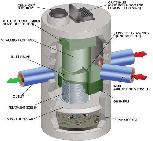
These components aid in sediment separation by directing the flow path of incoming water to allow for swirl concentration and gravity settling of particles to take place as noted in the above section. This is often done using an inlet flume and separation cylinder.
2. Bypass Strategies (Weirs, Baffles)
Well-designed bypass mechanisms are crucial to managing high flows and preventing resuspension and scour of previously captured pollutants. Many HDS devices are designed to handle a certain bypass capacity within the unit itself. When the bypass requirement from a peak storm event exceeds the maximum bypass capacity of the HDS unit, the unit can be placed offline with only treatment flows being directed to the device. In Figure 1, there are two weirs placed on both sides of the cylinder to address bypass internally for most sites.
3. Pollutant Retention (Sump)
The sump of an HDS unit is typically defined as the area from the invert of the outlet pipe to the bottom of the structure. Maintaining the right sump depth facilitates effective retention of pollutants (mainly sediment), even in the case of large 50- and 100-year storm events. If the sump is too shallow and a large storm event occurs, the increased flow of water can potentially resuspend the previously captured pollutants.. In Figure 1, the use of a separation slab further prevents resuspension by separating previously captured pollutants from the treatment area of the unit.
4. Trash and Debris Control (Screens, Cylinder and Baffle Extensions)
Screens play a pivotal role in capturing and containing trash and debris. Screen aperture size should be designed to be no larger than trash, which is often defined as anything larger than 5mm. Screen locations can vary based on the flow path of a given unit. In Figure 1, the screen is shown below the inlet flume and separation cylinder.
Retaining trash and debris is different than that of retaining sediment. Because these pollutants are floatable, the unit must be able to contain everything at the top of the water surface while still allowing water to pass through. This is typically done by extending the baffle or cylinder to the same height as the Hydraulic Grade Line (HGL) to prevent the escape of floatables.
5. Oil Removal (Baffles, Sorbent Packs, and Oil Booms)
Like trash and debris, oil has a lower specific gravity than that of water, therefore oil is neutrally buoyant on the water surface. In Figure 1, the oil baffle traps any hydrocarbons underneath the typical treatment path, which prevents oil from exiting the system during subsequent storm events. Oil Sorbent packs can also be added to some HDS units to further enhance or add to the unit’s oil removal capabilities.
6. Inlet and Outlet Optimization (Grated Inlets, Multiple Pipes, Angled Entries, Pipe Drop) Stormwater can enter an HDS unit at various locations, but it is important to note that not all units can handle the same quantity and configuration of inlets, and even if they can, the local regulations may not allow for any configurations outside of how that unit was tested. It is also critical to ensure treatment flows and bypass flows from all the combined inlet locations do not exceed the maximum rates in which the device was designed for.
Grated Inlets
Some units have the capability to accommodate a grated inlet. This can provide advantages on a tight site where you may need to eliminate a separate grated inlet structure. It is key to confirm that flow from the grated inlet follows the same path as water entering through a more typical inlet pipe.Oftentimes, this requires some sort of tray or pan to redirect flow towards the inlet side of the device.
Multiple Pipe Inlets and Angles
Many HDS technologies can accommodate several inlet pipes at various angles all at once, which allows for further minimization of structures and pipes on a site, but like the grated inlets above, maintaining a consistent flow path is key to the device functioning properly.
Pipe Drop
Most HDS units are designed and tested with minimal to no pipe drop from inlet to outlet, but some can account for a slight deviationin elevation change. Like the use of pans or trays with grated inlets, manufacturers may recommend an extra component to properly divert the flow from an inlet invert that is above the outlet to maintain a proper treatment flow path.
7. Maintenance Access (Appropriately Sized and Located Access Points)
For an HDS device to function properly, it needs to be inspected and maintained regularly. The use of a vacuum truck is generally the most effective and convenient method of removing pollutants from the system. Simply remove the manhole covers and insert the vacuum hose into the sump. The system should be completely drained down and the sump fully evacuated of sediment. In Figure 1, maintenance access is shown as the clean out.