Part I: That's a load ... off my mind.
For this two-part series, we’re going to delve into live loading. A majority of what will be covered in this article goes into design methodology. Additional detail will be included in the follow up, so make sure to check back for that second article.
Standard design live load vehicles on corrugated pipe can be mostly broken down into the following three groups:
-
Standard AASHTO live loading (H20/HS20, H25/HS25)
-
AASHTO LRFD loading (HL-93)
-
AREMA Cooper E-80 loading
Of course, there are additional “non-standard” live loads such as aircraft loading and construction loading, but we will save those for another time. Let’s begin by introducing the AASHTO Standard vehicles.
H20, HS20, H25, HS25 – AASHTO Standard Specification for Highway Bridges
Maybe you have thought to yourself, what is the difference between an “H” series live load and an “HS” series designation? The answer is easier than you would expect. The simple difference is an “H” series truck is a two-axle truck, while an “HS” series truck has multiple loaded axles (i.e. a semi-trailer vehicle). Quite simply, the number following the “H” is the gross tonnage of the design vehicle. To determine the total tonnage of the “HS” vehicle you will have to add one additional trailer axle load.
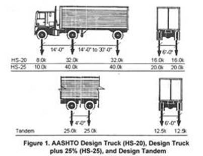
An “H20” or an “HS20” series truck will both have an 8,000-pound axle load for the drive axle and a 32,000 pound axle load for the axle(s) under the trailer. The only difference in these two vehicles is that the “HS20” truck has an additional 32,000-pound axle located under the trailer, which is separated by a minimum distance of 14’ – for a total load of 72,000 pounds. An “H20” truck only has one axle under the trailer and a total load of 40,000 pounds.
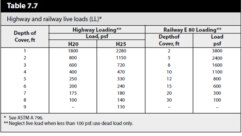
An “H25” or an “HS25” series truck will be almost identical – except the drive axle will be 10,000 pounds and the axle(s) under the trailer will be 40,000 pounds each. Figure 1 below illustrates the axle load and spacing breakdown for both HS20 and HS25 design trucks. Keep in mind the “H” equivalent of these loads simply removes the back axle. Table 7.7 below, from the NCSPA Design Manual, illustrates the live load breakdown for these two loading scenarios at various cover heights.
When it comes to pipe design, the distinction between “H” and “HS” load designations is mostly irrelevant. The second loaded axle is spaced far enough away that it will have a negligible impact on the pipe design. However, when designing a bridge or structure with a large enough span for the second axle to be placed on it, both “H” and “HS” loading scenarios must be evaluated.
HL-93 - Design Vehicular loading per the AASHTO LRFD Bridge Design Specifications.
AASHTO introduced a new design vehicle in 1993 with its updated AASHTO LRFD AASHTO LRFD (Load and Resistance Factor Design) Specifications. HL-93 live loading was established as part of the new LRFD methodology. This live load case is broken down in AASHTO LRFD Section 3.6.1.2 stating:
Vehicular live loading on the roadways of bridges or incidental structures, designated HL-93, shall consist of a combination of the:
- Design truck (HS20) or design tandem, and
- Design lane load (0.64 KLF uniformly distributed in the longitudinal direction)
This means that there are two loadings that need to be checked. HL-93 loading is representative of the worst case between these two loading scenarios. And yes, HS20 live loading can control for an HL-93 design check. Don’t let that cause you to stumble as you run through HL-93 loading scenarios.
-
The “design truck” and design lane load. The “design truck” is the same as the HS20 truck from the previous version of AASHTO (described above). The HS20 vehicle is shown in Figure 1 above.
- The “design tandem” and the design lane load. The design tandem shall consist of a pair of 25-kip axles spaced 4 feet apart and the transverse spacing of the wheels shall be taken as 6 feet. Figure 1, above, also shows the design tandem.
Load factors, dynamic load allowances, and other factors are then applied to these loads in the proper load combination(s) based on the LRFD spec.
Cooper E-80 - Design Vehicular loading per AREMA Specifications
Pipe designed under railroad loading should follow Cooper E-80 Live Loading per the American Railway Engineering and Maintenance-of-Way Association (AREMA) specifications. This loading consists of 80-kip axle loads spaced 5 feet on centers. The live load pressures at various cover heights can also be found in Table 7.7. It is easy to see that the live loads produced under Cooper E-80 loading are considerably larger than those of the AASHTO design trucks. It should also be noted that under AASHTO design vehicles, there is no live load felt above 8’ and 9’ of cover, respectively, for HS20 and HS25 design vehicles, while under Cooper E-80 loading live load pressures are felt for pipe up to 30’ of cover!