
FINITE ELEMENT ANALYSIS. HARD FOR HUMAN. EASY FOR COMPUTER.
WHAT IS FINITE ELEMENT ANALYSIS?
Can you solve this equation by hand? x + 4 = 7
How about this one? ![]()
Now we need to solve that another 1000 times to get our answer!
Many times engineers are able to use relatively simple methods or calculations that are proven to provide consistent and accurate solutions to everyday problems. Typically these calculations can be carried out with the use of a spreadsheet tool or can even be handwritten.
There are times, however, when the problem becomes too complex or too time consuming for it to be solved by simple methods. With the aid of computers, it is possible to use the finite element method to handle these complex situations via a finite element analysis (FEA).
A finite element analysis is the investigation of a specific object that is cut into smaller elements and a force is then applied to those elements. Those elements will deform and shift based on the properties assigned to them. Basically, the goal is to take an object, then squish it and stretch it to see if it breaks.
WHAT PROGRAMS ARE AVAILABLE FOR CULVERT ANALYSIS?
PLAXIS, CANDE, ABAQUS, and STAAD are a few examples of programs that can be used to model culvert structures with finite element analysis. Each program is different and has its range of capabilities. For example, some programs can only model in 2D while others can be modeled in 3D.
 |
 |
| CANDE FEA Cross Section | PLAXIS FEA 3D Rendering |
WHY USE FINITE ELEMENT ANALYSIS?
In broader terms, FEA saves people from creating actual physical models and then testing them with physical forces that could cost a lot of time and money. These analyses can help prove to a customer or a research study that a physical object will work or fail.
At a more specific level, the standards that govern culvert and buried bridge design are set by the American Association of State Highway and Transportation Officials (AASHTO). AASHTO requires the use of FEA for culvert and buried structures with deep corrugations such as BridgeCor® structural plate. This is so that the analysis can accurately represent the interaction between the structure and the surrounding backfill based on the mechanical properties of the metal and soils.
HOW DOES FINITE ELEMENT ANALYSIS WORK?
Imagine that you have a metal spring. Attached to that spring, you also have round spheres (nodes) on each end.
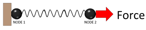
This is an example of a very simple finite element model and can help demonstrate how FEA works. If you apply a force to one node, the spring will elongate right? The distance of that elongation (or deformation) is linearly related to the force and is dependent on the stiffness of the spring. This is also known as Hooke’s Law, a fundamental law that is used as a basis to determine how elements will behave in a finite element model.
Adding another spring to this model adds to the complexity of the calculation necessary to predict the deformations happening at each node, because they become dependent on each other’s movement. So as you can imagine, when there are hundreds or even thousands of nodes, the use of a program could come in handy. Hooke’s law (F =Kx) now becomes a much more involved equation. This is where matrix theory is helpful and is what runs behind the scenes of an FEA program.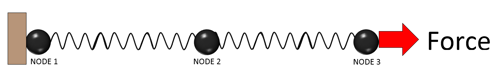

If we now arrange these springs to create a boundary, we can create a representation of physical blocks of materials such as steel, concrete, or soils. With this network of springs, nodes, and boundary conditions, we can predict how a finite element will behave when a force is applied.
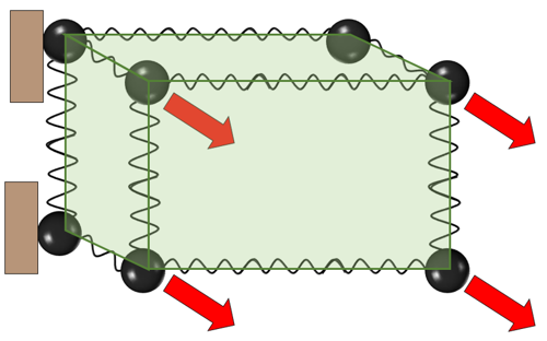
With enough elements, an FEA model may be created to represent virtually any object that can predict a variety of behaviors such as mechanical deformations, vibrations, heat transfer, acoustics, and even seismic.