
“An Uplifting Situation”
The design, manufacture and installation of Concrete, Corrugated Steel, Plastic and Steel Reinforced Polyethylene pipe happens every day for storm sewers and culverts. While most design engineers spent many hours in college learning about hydrology and hydraulics, how many spent time studying the buoyancy of pipe materials in the field? While most design engineers size storm sewer systems and culverts to pass the 10, 25, or 50 year rainfall event, how many have completed a free body diagram of the hydraulic forces on the inlet of that 96” diameter culvert they just specified for a roadway crossing?
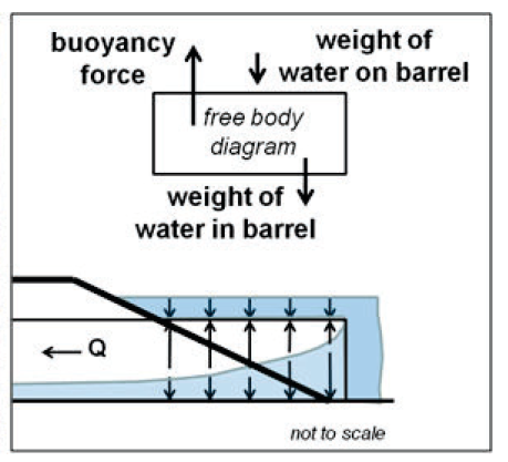
Flotation is the term used to describe the failure of a culvert due to the tremendous uplift forces caused by buoyancy. (FHWA-HIF-12-026)
buoy·an·cy /ˈboiənsē,ˈbo͞oyənsē/ noun
- The ability or tendency to float in water
- In physics, a force on an object making that object rise or move upward.
Why do I bring this up? As the Region Engineer for a pipe manufacturer covering multiple states, I tend to answer this question from customers almost every day.
Question: What do you recommend for the end of this large diameter pipe?
Answer: Cutoff wall and headwall.
“Positive engineering attention should be given to the need for providing protection at the ends of all pipe culverts having a height of 48 inches and larger” (FHWA 1974)
Piping is a phenomenon that begins with seepage along the outside of a culvert barrel, which progressively removes fill embankment material, forming a hollow similar to a pipe, hence the term “piping”. (FHWA-HIF-12-026)
Question: Why Cutoff walls and headwalls?
Answer: Cutoff walls provide protection from erosion caused by water swirling around at both the inlet and outlet ends of the culvert. Most short length culverts operate under inlet control which means there is usually a high headwater on the inlet end and high water velocity on the outlet end. Water impounded on the inlet saturates the soils and begins to swirl as the water enters the culvert. Saturated soils have the weakest bonds to their surrounding particles and the swirling motion of the water tends dislodge the soil particles from both under and around the pipe end. High water velocity coming out of the end of the culvert causes the migration of soils downstream of the culvert end. When this happens the soil loss (head cut) migrates upstream or under and around the pipe culvert end. A cutoff wall prevents water from flowing under the culvert reducing saturation and preventing erosion. When you reduce saturation you reduce the buoyant force caused by pore pressure in the underlying soils.
Headwalls, prevent piping alongside the culvert and in conjunction with a cutoff wall provide both dead load and friction forces that counter or offset the buoyant forces on the end of the culvert. The buoyant force on the inlet of a culvert is greatest when the headwater is at the top of the culvert. If the inlet has been improved by beveling the pipe you have both less weight in that portion of the pipe along with less beam stiffness to resist the buoyant force. Add debris blocking the pipe end and less water may enter the pipe reducing valuable dead load to resist the buoyant force.
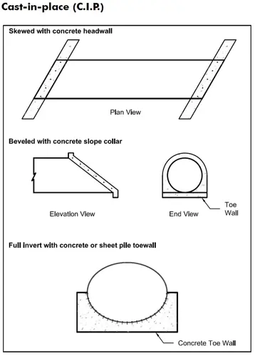
If we break all of this down, it is very simple to show that the addition of interlocking steel sheeting in short lengths with usually less than 1 truckload of concrete and you can eliminate "An Uplifting Situation."
For a more complete discussion on this subject matter, I suggest:
- Publication No. FHWA-HIF-12-026 April 2012, Hydraulic Design Series Number 5 Hydraulic Design of Highway Culverts 3rd Edition
- Iowa DOT Project HR-306 Investigation of Uplift Failures in Flexible Pipe Culverts
- Iowa DOT Project HR-332 Design Methodology for Corrugated Metal Pipe Tiedowns: Phase I
- Iowa DOT Project HR-362 Design Methodology for Corrugate Metal Pipe Tiedowns: Phase II