- Pipe
- Bridges & Structures
- Walls
- Stormwater Management
- Erosion Control
- Start a Project
- Knowledge Center
- Technical Documents
By Darrell Sanders, P.E., and Matt McCants, P.E.
Residents of urban and suburban areas of the country tend not to think much about how they travel to and from work, the store or a restaurant. However, those in rural parts of the country who live on a stretch of county roads with very few homes know that if it rains, the bridge may not be crossable.
Today, civil engineers typically build roads and highways in urban and suburban areas so they won’t be inundated with a rain event less than what’s considered a 100-year storm (Q-100), which means there’s a 1-percent chance the storm event will happen in any given year. When you live on a rural stretch of roadway, typically narrow with few other residents using the roadway, the design storm frequency the drainage structures will be unable to handle is much more common. In this example, the structure is designed to overtop the roadway during a three-year storm (Q-3), which means there’s a probability of the three-year storm event in one year = 1/F or 1/3 = 33.3 percent chance the runoff from the rainfall event will overtop the roadway. If you live down this stretch of roadway, you will be wondering if you can cross the drainage structure each time it rains.
p = probability
F = Recurrence interval or frequency
p (F event in one year) = 1/F
The probability of an F event occurring in “n” years is
p (F event in n years) = 1 – (1-1/F)^n
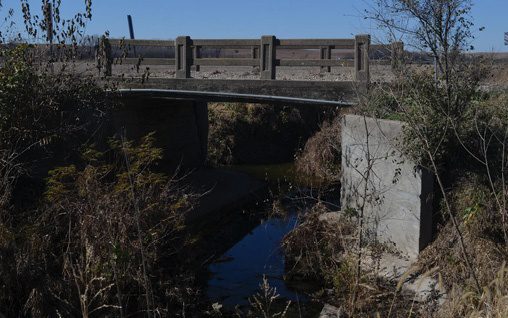
For this case study, we will be looking at a structure (Bridge No. 119) located on a gravel roadway in Wabaunsee County, Kan., 6.2 miles north and 2.7 miles east of Paxico, Kan., on Pioneer Road (see Figure 1). It crosses a tributary of Turkey Creek, and the average annual daily traffic (AADT) is 20 vehicles. The current structure is a 21-foot-span steel-beam structure with concrete deck. The approach roadway is 22 feet wide, and the structure roadway width is 17 feet wide. The steel beam structure was built in 1935 with a posted load rating of 9 tons (18,000 lbs.) and needs replacement due to structural deterioration.
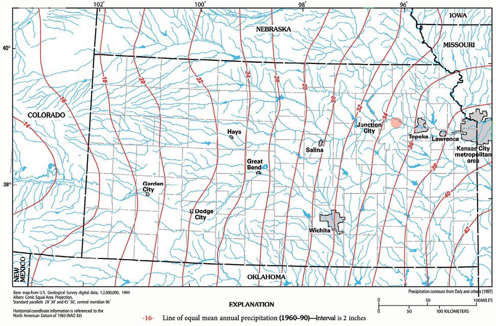
The contributing drainage area (CDA) for this structure is 6.4 square miles with land use of 20 percent pasture and 80 percent cultivated row crop farmland. The structure is in the floodplain of the Kansas River but, otherwise, has no other known controls affecting the water-surface elevation such as railroad, roadway bridges, dams, rock outcrops or levees. Watershed length is 4.4 miles with a main channel slope of 26.97 feet/mile. Figure 2 from the U.S. Geological Survey shows the average mean annual precipitation (P) intervals for the state of Kansas. The project location (red dot) shows P = 36 inches per year.
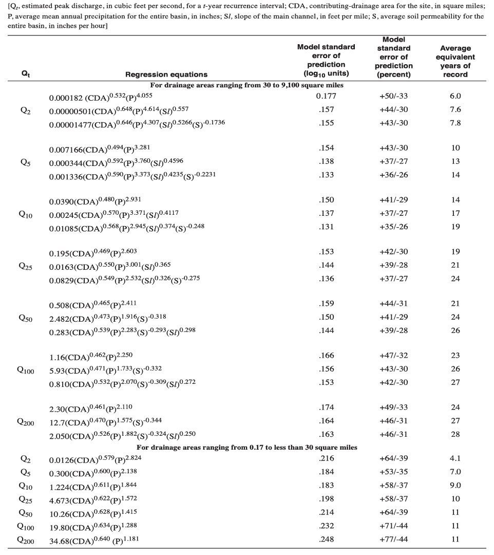
By utilizing the regression equations in Table 1 for the small drainage areas, the following peak-flow quantities by frequency in years can be determined for this unregulated stream in Kansas.
Q-2 = 920 cfs
Q-5 = 1,940 cfs
Q-10 = 2,820 cfs
Q-25 = 4,150 cfs
Q-50 = 5,240 cfs
Q-100 = 6,490 cfs
The existing steel beam has a low-chord elevation of 950.6 feet. This structure was surveyed, and the open area was determined to be just under 224 square feet of opening. The streambed elevation is 937.6 feet, and the top centerline of roadway elevation is 952.0 feet. In this location, the existing bridge had been performing well hydraulically since 1935.
Because single-span bridges are very expensive, it was decided to select a multi-barrel structure that performed very closely hydraulically to the original single-span opening. Multi-barrel large-diameter corrugated steel pipe (CSP) was selected because it’s the most cost-effective drainage structure available in the construction industry. The best way to begin the selection criteria is to closely match the open area of the existing structure with multiple barrels that will fit the existing elevation profiles of the roadway embankment. The open area of a 12-foot-diameter corrugated steel pipe (CSP) is equal to 113.1 square feet of opening, so placing two of these would provide 226 square feet of opening for further analysis by HY-8 for comparison of existing to proposed structures.
The USDOT Federal Highway Administration has free software available for use that automates culvert hydraulic computations (available at https://www.fhwa.dot.gov/engineering/hydraulics/software/hy8/).
This easy-to-use software enables users to quickly develop a site-specific analysis based on user inputs. The generated data is utilized to compare the above unregulated peak stream flows to the design discharge elevations. The flow calculations generated by the software will let us know if we can meet the design discharge flow of Q-3 of 1,300 cfs to see if it will pass through the pipe before overtopping the roadway.
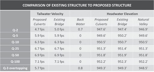
It’s common practice to grade the roadway embankment so overtopping flows happen to one side or the other and away from the bridge or culvert, so when overtopping occurs it’s less likely to damage the drainage structure. Roadway repairs are usually easier and less costly than structure repair. The roadway station and elevation data are included in the HY-8 analysis and are part of the overall hydraulic design. Once completed, we can also compare the headwater and tailwater depths along with tailwater velocities of the existing and proposed structure to see how closely the new structure performs to the old structure. In this project, some grading modifications to the approach roadway were completed to closely match the tailwater depths and velocities.
The comparison in Table 2 shows that the tailwater velocity and headwater elevations of the existing structure and proposed culvert are very close, including minor increases in back water for common low-flow events. This structure is quite the distance from any dwellings, livestock areas or agricultural buildings. There should be no concern for the similar proposed values shown in Table 2.
For this site, the design called for use of two 144-inch-diameter CSP culverts. The pipes utilize a galvanized coating, which has a history of providing good service life in this project. The pipes are fabricated using a 5- by 1-inch corrugation profile using a minimum wall thickness of 10 gage (0.1345 inches). This pipe has an allowable cover range of 1.5 feet to 39 feet for standard AASHTO HL-93 design vehicles.
The site calls for the bottom 18 inches of the pipe to be buried below the streambed elevation. This is an excellent design choice as it has several advantages. First, it protects the invert of the pipe from abrasive forces. Abrasion from stream flows carrying sediment can attack the coating of the pipe and decrease the service life of the invert. By burying the invert, it’s protected from most of the impact of the stream flows.

Second, the bottom 18 inches of the pipes only comprise about 7 percent of the available flow area within the pipe. Therefore, most of the flow area is still available for use. Also, the headwater depths at normal flows will be lower with a buried invert round structure, because there is more flow area available near the flowline of the stream. Finally, by burying the structure, the crown elevation of the pipe is lowered, allowing for a lower roadway elevation over the structure. This can help minimize embankment construction costs around the structure.
Another important element of the design of the structures is the end treatment. The 144-inch-diameter pipes are designed to utilize full beveled ends. This significantly improves the inlet function of the culverts as compared to leaving the ends of the pipe projecting from the ends of the embankment. To help protect the cut edges of the bevels, large riprap stone is utilized on the embankment slope to minimize flow forces against the cut edges of the culvert as well as protect the slope from erosive forces during high-flow events.


The stream is widened at the crossing to accommodate the culvert structures. To minimize the width of the culvert installation, the pipes are being installed with only 12 inches between the twin structures. This is just enough width to allow the pipe sections to be joined, but it’s inadequate space to permit the placement and compaction of conventional granular fill. Therefore, a flowable fill material is specified as backfill for the space between the two structures from the streambed level to the top of the pipes. The use of flowable fill eliminates the need for manual haunching of the material as would be required for granular materials. Also, because it’s a cementitious material, it doesn’t require compaction to gain its strength.
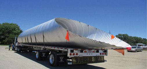
The use of CSP simplifies the installation of these culverts in many ways. Primarily, CSP is available in long lengths even in large diameters such as the 144-inch-diameter pipe used on this project. The 10-gage pipe weighs approximately 282 pounds per lineal foot, so a 20-foot section would weigh 5,640 pounds.
The plans call for a shaped bedding to be excavated to accommodate the invert of the pipe, as it lies below the elevation of the streambed. The bedding needs to be a granular material, generally 4 to 6 inches thick, and doesn’t need to be compacted. By leaving the top of the bedding loose, the pipe corrugations can nestle into the bedding, and the bedding will provide uniform support to the bottom of the pipe.
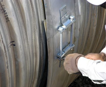
The pipe sections are attached using conventional bands. The most widely used connecting band for CSP is a semi-corrugated band referred to as a HUGGER® band, which has an annular corrugation formed on the outer edges of the band. These corrugations index into rerolled annular corrugations at the ends of each pipe when the band is assembled and tightened around the pipes. The attaching bands keep the pipes aligned properly, providing a soil-tight connection and pull-apart resistance to loads during the backfilling operation.
Backfill material should consist of granular materials as directed by the project engineer. The backfill should be placed in 6- to 8-inch loose lifts and compacted to a minimum 90-percent density after placement. It’s important that the fill be kept balanced across the pipe, with a maximum 2-foot differential in backfill height from one side of the pipe to the other. This installation utilizes flowable fill material between the barrels. The balanced placement of the fill materials must be met with regards to the flowable material between the pipes as well. Additionally, it’s important to take care that the initial lifts of flowable fill are kept at a level that won’t produce enough flotation forces to lift or displace the pipe.
After the backfill has been placed around the pipe, the invert can be filled using a small piece of excavation equipment to push the material into the pipe. Care should be taken to keep a cushion of backfill between the tracks of the construction equipment and the pipe walls to avoid damaging the coating on the pipe. The beveled ends of the pipes can be cut at the plant or cut in the field. For large bevels such as these, some temporary bracing may be necessary to keep the beveled ends in their proper shape during the backfilling process.
Rural county roadways carry small volumes of traffic on any given day. The low volume of traffic along with availability of short-detour alternate routes along with low probability of damage to property should the road or structure washout allows design professionals to select drainage structures that overtop roadway embankments at smaller, less-intense rainfall events. This design was utilized because it very closely matched the hydraulics of the original bridge that had performed well for 85 years.

The large benefit to the county was the installed cost savings of a multi-barrel large-diameter CSP structure compared to a multi-barrel reinforced concrete pipe (RCP) or reinforced concrete box (RCB) culvert. CSP is designed to meet the necessary structural design criteria of AASHTO HL-93. Additionally, this design was enhanced with flowable mortar backfill between the pipe, fully beveled ends, rock riprap for hydraulic scour protection along with a buried invert for metal-loss protection from runoff bedload abrasion. Overall, this is a long-term, highly cost-effective and hydraulically efficient structural replacement solution for small-span bridges.
Sources
The Professional Development Series is a unique opportunity to earn continuing education credit by reading specially focused, sponsored articles in Informed Infrastructure.
If you read the following article, display your understanding of the stated learning objectives, and follow the simple instructions, you can fulfill a portion of your continuing education requirements at no cost to you. This article also is available online at v1-education.com.
Rural stream crossings are not designed to the same hydraulic capacity as municipal, state and federal stream crossings.
Hydrology is site-specific and based on rainfall and stream data equations developed by U.S. Department of the Interior and U.S. Geological Survey.
Hydraulic design of culverts is an iterative process, and it will take multiple attempts to determine and develop a final design solution.
Scour protection is an important part of both the hydraulic and structural design of culverts, and it should not be overlooked by the designer.