- Pipe
- Bridges & Structures
- Walls
- Stormwater Management
- Erosion Control
- Start a Project
- Knowledge Center
- Technical Documents
By Darrell Sanders, P.E.
Piping systems are typically designed with the service loads in mind. Many utilities are subjected to highway loads, so the design vehicle frequently reflects a vehicle described by the American Association of State Highway and Transportation Officials (AASHTO) design code such as an HS-20 or HL-93 truck. However, there are many other vehicular loads that the pipes will likely need to support as well. Many of these are loadings from vehicles used during installation of the utilities. Excavators, dozers, front-end loaders, roller compactors and other equipment are commonly used on projects that involve pipelines. Many times, these pieces of equipment are operating at cover depths less than the final cover that will support the highway vehicles. Contractors need to know how much cover is required to operate the various pieces of equipment they use on projects.
Flexible buried pipes generally have high thrust capacities but must be protected from concentrated surface loads like those produced by construction vehicles. Methods have been developed to help evaluate the impact of those loads from wheeled vehicles, but similar resources for evaluating loads from tracked vehicles are not as prevalent. The methodology presented in this article leverages a design method developed for wheeled vehicles and provides a means of using it for tracked vehicles as well.

From a loading standpoint, the pipes are indifferent to which type of vehicle is operating over it. The pipe experiences a live load associated with those vehicles passing above it. AASHTO describes a methodology for distributing wheel loads from the surface to the crown of the pipe using a live load distribution factor. It states that for flexible buried structures, each side of the live load pressure distributed area will increase by 1.15 feet for each foot of cover from the ground surface to the crown of the pipe. That means that if the footprint of a wheel load is 20 inches wide and 10 inches long at the ground surface, then the same load would be distributed 1 foot below the surface over an area 33.8 inches wide and 23.8 inches long. This distribution should remain the same whether the contact area from the live load vehicle was from a rubber tire, steel tracks from a dozer or the square pad from an outrigger plate.
There are many different methods used to establish the minimum cover required for construction vehicles. However, most methods and tables focus on wheel loadings. To establish minimum cover requirements for tracked vehicles, a methodology designed for use with wheeled vehicles was modified. The methodology was developed by Dr. J.M. Duncan and R.H. Drawsky in the 1980s. This methodology is referenced in the “Corrugated Steel Pipe Design Manual” published by the National Corrugated Steel Pipe Association (NCSPA).
The design methodology centers on the required plastic moment capacity needed by the pipe to prevent a bending failure within the pipe wall under the influence of live loads. The methodology states that the required plastic moment capacity is computed as follows:
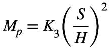
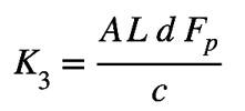
Where K3 is defined as:
In which: Mp = plastic moment capacity (k-ft/ft)
S = span or diameter (ft)
H = cover depth over crown (ft)
AL = axle load for the design vehicle (kips)
AL is the load supported on a single axle or on tandem axles if the spacing between the axles is less than 1/3 of the span of the culvert
d = corrugation depth (ft)
Fp = factor of safety against the development of a plastic hinge (dimensionless)
c = coefficient whose value depends on the degree of compaction of the backfill
c = 69 for a compaction level equal to 90-percent standard AASHTO
c = 115 for a compaction level equal to 95-percent standard AASHTO
Where: Fp = 1.3 for 0 < H/S ≤ 0.1
Fp = 1.6 – 3(H/S) for 0.1 < H/S < 0.2
Fp = 1.0 for H/S > 0.2
This methodology provides the plastic moment capacity required for the pipe under the influence of wheel loads. For a given pipe with a known plastic moment capacity, it can be manipulated to provide the required cover depth to safely operate a wheeled vehicle over it.
To apply this methodology to tracked vehicles, we’ll manipulate the track load and convert it to an equivalent axle load for a wheeled vehicle. We’ll begin the process by looking at the footprint from the tracked vehicle and determining the live load pressure exerted by the tracked vehicle at a depth equal to the crown of the pipe. This will be accomplished using the same methodology to spread the live load as described by the AASHTO code.
First, information about the vehicle to be analyzed is required. Specifically, we need to know the dimensions of the tracks and the operating weight of the vehicle. This information is generally available from equipment manufacturers. The ground pressure at the bottom of the tracks can be determined by dividing the total weight by two (to get the weight supported by each track) and then dividing that value by the area of the track.
For instance, let’s assume a vehicle has an operating weight of 100,000 lbs. The weight supported by each track is 100,000 / 2 = 50,000 lbs. Let’s also assume the track is 2 feet wide and 10 feet long. The area of the track is 20 square feet, which means the pressure at the bottom of the track would be 50,000 / 20 = 2,500 psf.
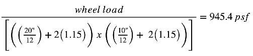
Let’s also assume that the pipe we’re evaluating will have 2 feet of compacted cover over it. We then need to determine what the pressure from the track would be 2 feet below the ground surface. It was stated previously that, per AASHTO methodology, the length of the sides of the vehicle footprint will increase by 1.15 feet for each foot of depth it is distributed through. At the surface, the track width was 2 feet. Therefore, at 2 feet of depth, the length of the distributed area would increase to 2 feet + 2(1.15) = 4.3 feet. Similarly, the length of the track would extend to 10 feet + 2(1.15) = 12.3 feet. This results in a new distributed area of 12.3 feet x 4.3 feet = 52.9 square feet. The 50,000-lb. vehicular weight distributed over 52.9 square feet results in a pressure of 945.4 psf at the crown of the pipe.
To use the Duncan/Drawsky method previously described, we must establish an axle load that would produce a crown pressure equivalent to that generated by the tracked vehicle in our example. To do this, we’ll utilize the AASHTO code for the distribution of wheel loads. AASHTO states that for highway vehicles, the surface footprint of a wheel is 20 inches wide and 10 inches long. Therefore, to determine an axle load that would produce a pressure at 2 feet of depth equal to that of the tracked vehicle described above and using the AASHTO method of pressure distribution through soil would be as follows:

Therefore:
Solving for the wheel load results in a value of 11,750 lbs. for the wheel load. Since an axle consists of two-wheel loads, the equivalent axle load would be 2(11,750) = 23,500 lbs. or 23.5 kips. This axle load then could be plugged into the Duncan/Drawsky methodology to determine a plastic moment capacity required for the pipe in question to safely support the construction vehicle.
If the methodology were applied to a particular pipe, the results might look something like the following:
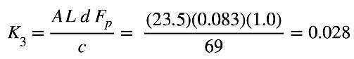
Let’s assume a 96-inch-diameter corrugated steel pipe using a 5- by 1-inch corrugation profile is in place, and the tracked vehicle needs to pass over it. In that case, we would begin the analysis by computing the factor as follows:
The required plastic moment capacity then would be computed as:
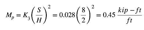
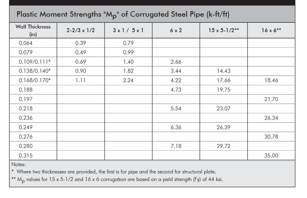
The NCSPA Steel Pipe Design Manual has a table of plastic moment capacities and shows that for a corrugated steel pipe utilizing a 5- by 1-inch profile, the plastic moment capacity of that wall with a 16-gage wall thickness is 0.79 kip-ft/ft and would satisfy this requirement.
Although the pipe could handle the moment demands placed on it in this example, it is important to note that if the pipe didn’t have enough bending capacity, one easy fix would be to increase the density of the backfill used around and over the pipe. The Duncan/Drawsky methodology allows for a 40-percent reduction in the moment demand by using a backfill material compacted to 95-percent minimum density rather than a 90-percent density. This reflects the loads are distributed more efficiently and pipes are better supported by stiffer, more highly compacted backfills.
There are a few other items that should be mentioned regarding the use of this process. It would be important to ensure the distance between the tracks on the vehicle is great enough that the distributed area beneath each of the tracks do not overlap. If they do, the combined pressure in the overlap area should be used in the design. However, for most minimum-cover cases, the track or wheel loads are far enough apart that there are no overlapping pressure zones.
Also, it is important to note that the track widths have a significant influence over the equivalent axle load representing that piece of equipment. For instance, if the same 100,000-lb. vehicle described above only used a 1-foot-wide track (assuming a 5:1 width-to-length ratio for the tracks), the equivalent axle load for that vehicle would be 48.9 kips rather than the 22.3 kips for the 2-foot-wide tracks. Similarly, if the tracks were increased to 3 feet wide, the equivalent axle load decreases to 12.8 kips.


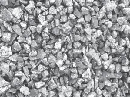

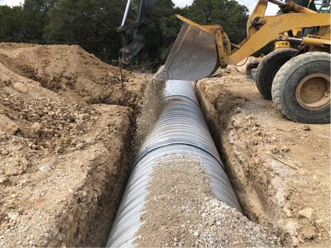
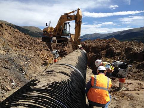
Figure 4. Examples of Acceptable Backfill (above images)
Another important item to mention is that the pressures used in the calculations above only consider the operating weight of the construction vehicle. This would be similar to the weight of a vehicle just crossing over the structure at a steady speed. It does not include any other considerations such as impact loads, additional payload being carried, boom/arm extensions, turning forces or other considerations. If a piece of equipment is going to be operating over a buried pipe, all those factors must be accounted for to ensure the maximum pressure beneath the tracks does not exceed the capacity limits for the pipe. This is important, as track pressures can vary greatly beneath a structure when the equipment is in operation. For this reason, it is prudent for a factor of safety to be applied when evaluating the minimum operating cover over the pipe.
Used properly, the methodology outlined in this article should provide a means of evaluating the pressures beneath the tracks of a construction vehicle and determining if it can operate safely over a buried pipe with a defined minimum cover.
Darrell Sanders, P.E., is chief engineer for Contech Engineered Solutions LLC. He holds a B.S. degree in Civil Engineering from the University of Cincinnati and an M.B.A. from the University of Dayton. He has been a registered Professional Engineer in Ohio since 1996. Darrell is active in several industry committees, including NCSPA, AASHTO, ASTM and TRB.
Click on the button below to start the quiz for this course. Your score will be tabulated while you wait, and you will receive your certificate upon completion if you correctly answer eight or more questions.
Registration on v1-education.com is required to access the quiz. Use the "Sign Up" link in the top right of v1-education.com to register. If you are already registered simply enter your credentials to access the quiz.
The Professional Development Series is a unique opportunity to earn continuing education credit by reading specially focused, sponsored articles in Informed Infrastructure.
If you read the following article, display your understanding of the stated learning objectives, and follow the simple instructions, you can fulfill a portion of your continuing education requirements at no cost to you. This article also is available online at v1-education.com.
At the conclusion of this article, the reader should be able to understand:
Click on the button below to start the quiz for this course. Your score will be tabulated while you wait, and you will receive your certificate upon completion if you correctly answer eight or more questions.
Registration on v1-education.com is required to access the quiz. Use the "Sign Up" link in the top right of v1-education.com to register. If you are already registered simply enter your credentials to access the quiz.