- Pipe
- Bridges & Structures
- Walls
- Stormwater Management
- Erosion Control
- Start a Project
- Knowledge Center
- Technical Documents
By Matthew Stovall, P.E., and Daniel Priest, P.E.
— Chinese philosopher, Lao Tzu
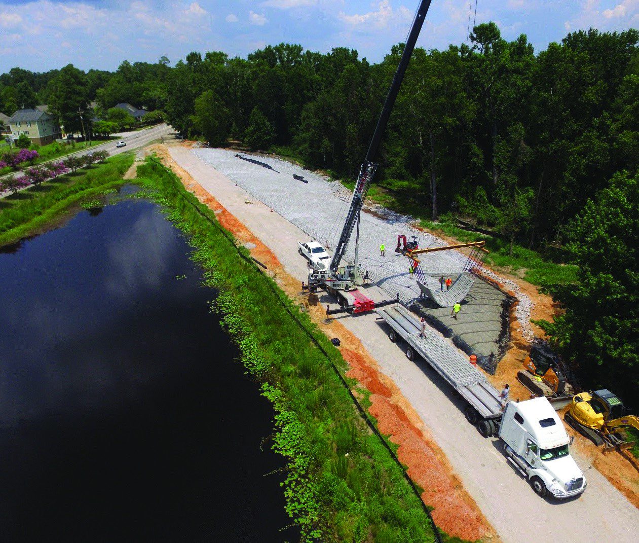
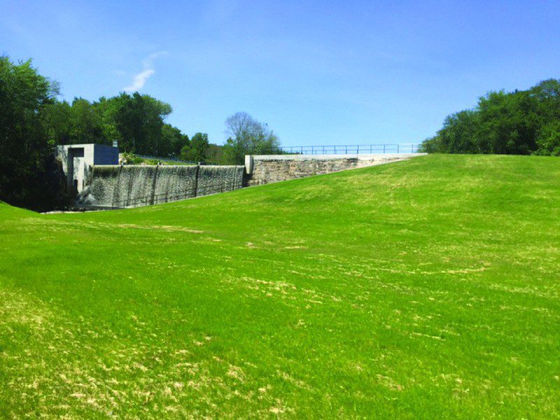
When left uncontrolled, water has created the deepest of canyons and destroyed countless properties. Sediment transport in streams and rivers is inevitable, but erosion must be controlled in critical areas for safety and economic reasons. Stream restoration and stabilization may require the use of armoring countermeasures to provide lateral or vertical stability to a stream. Articulated concrete block (ACB) revetment systems provide permanent erosion protection against the hydraulic forces of moving water. They are used when vegetation, soil remediation or other forms of hard armoring are unstable or unsuitable for a given hydraulic event or where the consequence of failure is not acceptable.
What Is an ACB?
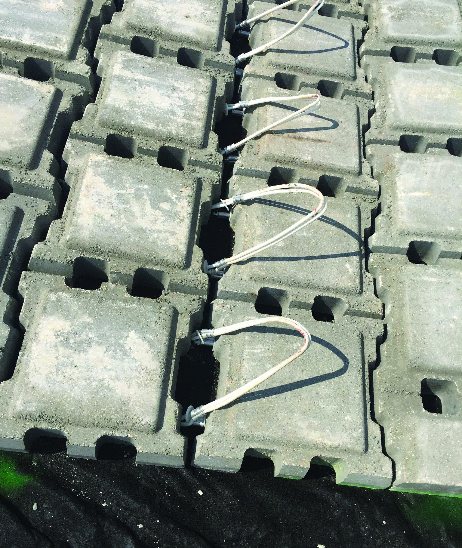
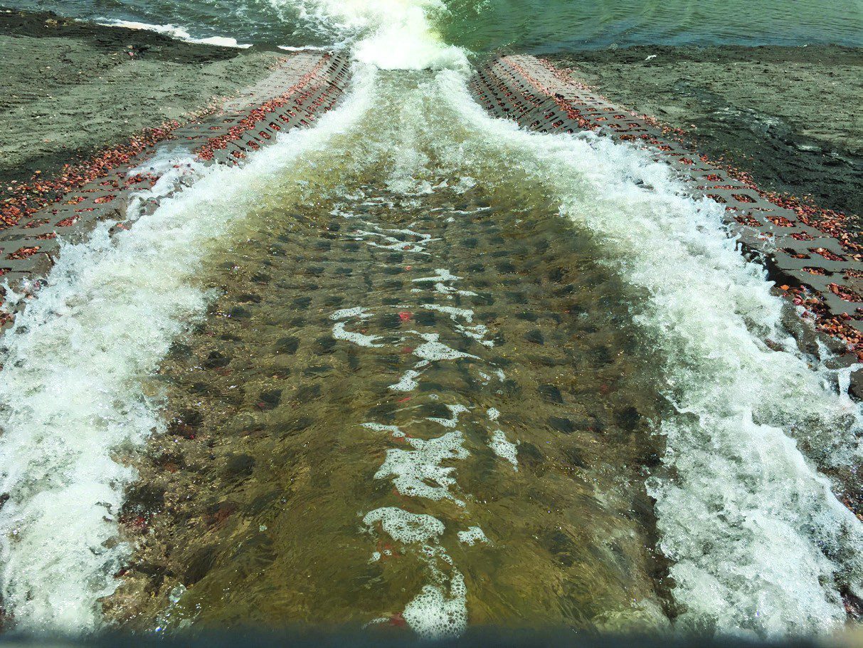
An ACB system consists of a flexible, interlocking matrix of concrete blocks that are commonly used to provide protection against erosion from flowing water. The individual units are connected by cables or geometric interlock (see Image 1). The term “articulated” refers to the system’s ability to conform to a subgrade through reasonable changes in elevation. The articulating feature allows them to be effectively placed at bends and regions of vertical change. ACBs provide a surface over which water can flow, protecting against erosive forces (see Image 2).
ACBs generally sit on top of a filter layer, which retains the subgrade soils while allowing infiltration and exfiltration. The filter layer may consist of a geotextile, a graded granular layer, or both. The filter layer must be sized to retain soil particles and prevent hydrostatic pressure buildup.
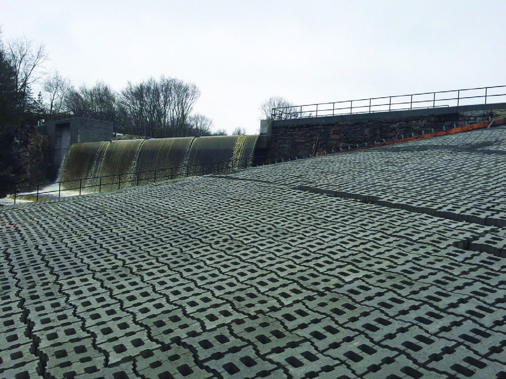
ACBs provide a flexible option to other erosion control countermeasures, such as riprap, soil cement, gabions, and grout-filled mattresses. They can be used in a broad range of erosion control applications with success. Since ACB systems have a very high armoring potential, their use is not limited to subcritical flow or locations of low turbulence. ACBs have been successfully used in conditions where high velocities are generated such as spillways, grade-control structures and culvert outlets. They have been successfully tested in laboratories at full-scale to resist velocities in excess of 30 feet per second. Typical applications for ACBs include channel lining, dam spillway armoring, embankment protection, and low-water crossings as well as many other hydraulic protection applications where soil erosion over large areas or where concentrated flow is present. ACB systems can be either closed-cell systems to minimize exposed subgrade areas or open-cell systems to allow for increased infiltration, exfiltration, and vegetative growth. In the proper climate, open-cell ACBs can be almost fully vegetated to provide an almost hidden barrier of protection (see Image 3).
ACB Performance
Like any other designed system, it’s important to be able to predict how an ACB system will perform. Designers often have the following questions:
• How is the appropriate thickness determined?
• How can the level of safety be determined, and what should it be?
• How are alternatives compared on an equivalent basis?
Predicting the performance of an ACB system can seem complicated, but in reality the task is similar to commonly used engineering practices. In other words, it’s like any other Factor of Safety calculation for a given condition: if the stabilizing forces are greater than the destabilizing forces, then theoretically the system should perform. In practice, designers typically look for a system where the stabilizing forces are at least 50 percent greater than any destabilizing forces (a minimum safety factor of 1.5) for a specific design condition. In some cases, designers select a higher or lower factor of safety, depending on the critical nature of the project and the reliability of the input parameters.
ACB usage dates back to the mid-1970s, when the former Soviet Union conducted tests and constructed block erosion systems (Clopper, 1991). In 1986, the Construction Industry and Research Information Association (CIRIA) documented testing of block systems at Jackhouse Reservoir in the United Kingdom (Hewlett et al, 1987). In 1988 and 1989, the Federal Highway Administration (FHWA) funded laboratory testing of ACB armored embankments (Clopper and Chen, 1988; Clopper, 1989). This testing and others resulted in the development of ACB design and analysis methods for performance prediction.
The first moment-stability analysis method to determine the safety factors for particles rotating out of a bank was prepared by Stevens and Simons (1971) and focused on coarse granular material. Simons and Senturk (1976) presented a similar analysis for riprap, which was adapted for use in determining ACB system stability by Clopper (1991). Other variations of the Simons and Senturk stability include Lagasse et al (2001), Harris County Flood Control District (2001), NCMA (2006) and HEC 23 Design Guideline 8.
All of these ACB design methods included the calculation of a single factor of safety intended to represent the entire system. The only stabilizing force was conservatively assumed to be the weight of the block itself (contributing a drag force), while destabilizing forces arose from both flowing water (in the form of applied lift force) and from the force of water impacting projecting edges. Although the geometry of the entire channel—a simple trapezoid—was taken into account, the calculated factor of safety made no reference to any specific location or block orientation; it was effectively a “worst-case” value. At the same time, there was no obvious method to directly calculate the applied lift and drag forces from the flowing water. For convenience, the magnitudes of both were assumed to be approximately equal and comparatively small by comparison to the other destabilizing forces, particularly the overturning force generated by the impact of flowing water on an arbitrary projecting edge.
“State of the Art” ACB Design Calculations
Modern ACB design makes use of a formulation of the factor of safety devised by Dr. Amanda Cox (2010), which actually consists of four separate equations corresponding to different orientations of the individual blocks and the direction of overturning (see Figure 1). Each one of these formulas uses specific, defined geometric characteristics of the block for the moment arms of the applied forces and calculates an applied lift and drag force. Therefore, understanding the definitions of the specific geometric characteristics and how they are measured is crucial to evaluating any ACB system.
The weight of the block is still conservatively considered the only stabilizing force. The same destabilizing forces still apply with the crucial difference that this design method includes a way of describing expected lift forces in the form of a new characteristic: Block System Lift Coefficient. Each applied force is associated with a specific moment arm, each of which are characteristic of a given ACB system.
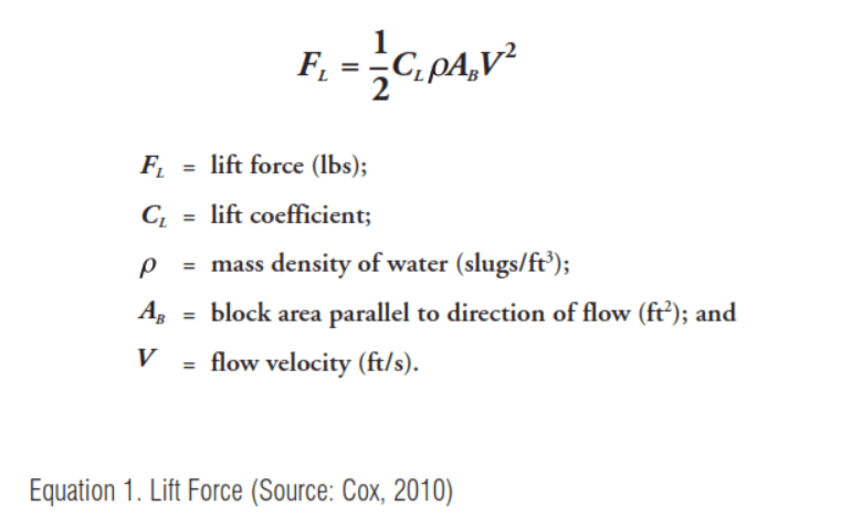
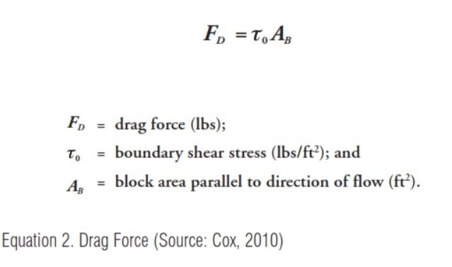
In calculating the lift and drag forces acting on a block, the surface area of the block exposed to flow, AB, must be known (see Equations 1 and 2). This area should be determined as accurately and precisely as possible and should exclude any areas within the block that are open (“open-cell” blocks have such openings). For a block with a flat, unvarying top surface with tapered sides down to a large block base, the AB is only the top surface of the block with no credit being allowed for the area of taper down to the base. For blocks which have a top surface that is not flat or even, the horizontal projected area should be used. If the AB is overstated, then both the lift and drag forces will be overestimated and the resulting calculated factor of safety will be inflated.
Each of the four safety factor equations include terms that are combinations of applied forces and moment arms. These moment arms are just the physical distances between where the forces act and the relevant overturning point (see Figure 1 for overturning points P, M, O and Bed). These distances are all related to the height, width and length of the individual blocks. Common among all of the equations is the first moment arm, l1, which is defined as half the height of the block. Since the center of mass of any block is located in the middle of the block, there will always be a component of the mass that acts in a destabilizing direction. Similarly, there will always be a component of the mass acting in a stabilizing direction. The other moment arms will be half the length, l2, half the width, l5, and half of the maximum diagonal distance from the center of mass, l7.

For the applied lift forces, the point of action is assumed to be the center of the top of the block. The moment arms will be the same as for the stabilizing mass component but are called l4, l6, and l8, respectively. The remaining moment arm, l3, is the moment arm for the drag force assumed to act at the top of the block. It is the full height of the block.
The eight moment arms and the area of block parallel to the direction of flow are characteristics of the blocks that make up a system and should easily be obtained from a manufacturer. If the block dimensions are not provided, they can be determined from direct measurement of the block.
The magnitude of these applied moments may be calculated with comparative ease, once all the geometric characteristics are known or calculated. But the orientation of the individual block makes a difference in their stability (i.e, the resulting factors of safety). For example, a block located in the bed of a channel at a 0.5 percent slope is much farther away from being overturned (much greater force is necessary to displace the block) than a block located on the 2H:1V (50 percent) side slope of a channel. For a block oriented like that, much less force is needed to produce displacement.
The final required geometric characteristic of the blocks, the Block System Lift Coefficient (CL), is not easily calculated and can only be obtained through performance testing in accordance with ASTM D-7277, in conjunction with analysis in accordance with ASTM D-7276. CL is a geometric characteristic that takes into account the block’s shape, weight and interactive friction resistance. This coefficient is a major advance in ACB design, effectively enabling an understanding of the factors of safety against overturning over several points and from different applicable orientations. Developed in 2010, the Block System Lift Coefficient is obtained by using threshold conditions (i.e., the flow conditions in testing that led to failure, or the maximum flow available at a testing facility if failure does not occur) to determine the actual lift force that was applied to the individual blocks during testing.
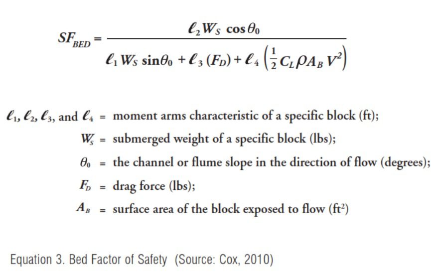
Since the ASTM test flume is rectangular with no side slopes, only the bed factor of safety is required for evaluation of block stability. At the threshold conditions, the factor of safety is assumed to be 1, and the bed factor of safety equation (Equation 3) can be set to solve for the Lift Coefficient, CL, (Equation 4).

The block system lift coefficient is unique for each tested system. This coefficient, while generally determined for a tested block, can be conservatively used for any thicker block that has the same footprint as the tested block. This is considered conservative on two counts: the thicker block will be heavier than the tested block (producing greater drag force and thus greater stability) and there will be more “interblock restraint” or resistance to movement based on interaction with adjacent blocks (which is not separately quantified).
Conclusion
ACBs have been practically utilized for more than 40 years for the protection of embankments, channels, spillways and other critical hydraulic structures. Their performance has been tested in laboratories as well as through thousands of installations. Factor of Safety methodologies for ACBs today now account for the lift associated with high velocities. The design of ACBs has evolved to better predict their performance.
In the end, the procedure for predicting ACB performance is simply a comparison of the forces acting to overturn blocks versus the forces acting to keep the blocks in place. The factor of safety calculation is little more than a moment-stability analysis. Most of the input parameters are easily determined through geometry and the remaining parameter emerges from testing via ASTM D-7277. In this way, any block may be compared to any other block, as long as both have been tested and the geometric characteristics are known.
References
ASTM D-7276, “Standard Guide for Analysis and Interpretation of Test Data for Articulating Concrete Block (ACB) Revetment Systems in Open Channel Flow.”
ASTM D-7277, “Standard Test Method for Performance Testing of Articulating Concrete Block (ACB) Revetment Systems for Hydraulic Stability in Open Channel Flow.”
Clopper, P.E., 1989. “Hydraulic Stability of Articulated Concrete Block Revetment Systems During Overtopping Flow,” Rep. No. FHWA-RD-89-199, Federal Highway Administration, McLean, VA.
Clopper, P.E., 1991. “Protecting Embankment Dams with Concrete Block Systems,” Hydro Review, 10(2), 54-67.
Clopper, P.E., and Chen, Y.H., 1988. “Minimizing Embankment Damage During Overtopping Flow,” Rep. No. FHWA-RD-88-181, Federal Highway Administration, McLean, VA.
Cox, Amanda L., 2010. “Moment Stability Analysis Method for Determining Safety Factors for Articulated Concrete Blocks,” Colorado State University, Fort Collins, CO.
Harris County Flood Control District (HCFCD), 2001. “Design Manual for Articulating Concrete Block Systems,” Ayres Associates, Houston, TX.
Hewlett, H.W.M., Borman, L.A., Bramley, M.E., 1987. “Design of Reinforced Grass Waterways,” Construction Industry Research and Information Association, Report 116, London, UK.
Lagasse, P.F., Zevenbergen, L.W., Schall, J.D., and Clopper, P.E., 2001. “Bridge Scour and Stream Instability Countermeasures: Experience, Selection, and Design Guidance,” Hydraulic Engineering Circular No. 23, Federal Highway Administration, Washington, DC.
National Concrete Masonry Association (NCMA), 2010. “Design Manual for Articulating Concrete Block (ACB) Revetment Systems Second Edition,” Publication No. TR220A, Herndon, VA.
Simons, D.B., and Sentürk, F., 1976. “Sediment Transport Technology,” Water Resources Publications, Littleton, CO.
Stevens, M.A., and Simons, D.B., 1971. “Stability Analyses for Coarse Granular Material on Slopes,” River Mechanics, H.W. Shen, ed., Vol. 1, Colorado State University, Fort Collins, CO, 17-1–17-27.
Authors
Matthew Stovall, P.E., is the Senior Hard Armor Design Engineer for Contech Engineered Solutions and provides technical support for erosion control and coastal protection projects in North America. He is a graduate of Georgia Institute of Technology in Civil Engineering and also holds a Certificate in Coastal Engineering from Old Dominion University.
Daniel Priest, P.E., is the Hard Armor Solutions General Manager for Contech Engineered Solutions. He is a registered professional engineer with more than 20 years of experience in design and construction of geotechnical and hydraulic structures. He holds a B.S. in Civil and Environmental Engineering from the University of Cincinnati and an M.S. in Civil and Geotechnical Engineering from Northwestern University in Evanston, IL.
The Professional Development Series is a unique opportunity to earn continuing education credit by reading specially focused, sponsored articles in Informed Infrastructure.
If you read the following article, display your understanding of the stated learning objectives, and follow the simple instructions, you can fulfill a portion of your continuing education requirements at no cost to you. This article also is available online at v1-education.com.