- Pipe
- Bridges & Structures
- Walls
- Stormwater Management
- Erosion Control
- Start a Project
- Knowledge Center
- Technical Documents
By Joel Hahm, P.E.
Structural-plate buried structures consist of multiple metal plates that are corrugated, shaped to a specific curvature, hot-dipped galvanized (when made of steel), and bolted together in the field to construct large culvert or clear-span arch bridge crossings. After assembly, they are backfilled using granular soil to complete the bridge crossing. They are considered flexible structures that work via soil-structure interaction, where the structure and surrounding engineered backfill work together to support the design loads.
Structural plate has been in use for more than 90 years. It originally served as a large-diameter alternative to corrugated metal pipe (CMP) for use in hydraulic applications where CMP could not be efficiently built large enough to satisfy hydraulic requirements or where bottomless (arch- or box-shaped) structures were needed. Original corrugation profiles were relatively shallow (6” x 2” or 9” x 2.5”), which limited the available structural-plate span length.
Since the development of deep corrugation profiles (those with greater than 5” corrugation depth) about 40 years ago, there has been a gradual increase in the use of structural plate for longer-span hydraulic crossings and grade-separation applications where conventional bridges have historically been used. This has resulted in the emergence of “Flexible Buried Bridges,” which are structural-plate structures with a span of greater than 20 feet—the AASHTO definition for the minimum span of a structure considered a bridge.
Today, flexible buried bridges are widely considered an attractive and economical alternative for short- to medium-span conventional bridge crossings. They offer a wide range of benefits, including basic economy, construction advantages, ease of transportation, environmental benefits, low maintenance costs, increased resilience and other factors. The use of these structures has been made possible by advancements in design and analysis tools, manufacturing capabilities, materials, and development of deeper corrugation profiles to allow for longer spans, heavier loads and higher cover.
Flexible buried bridges have demonstrated excellent performance in areas impacted by seismic events. These types of structures have historically performed very well compared to other bridge types in seismic events, typically remaining functional as a lifeline and often requiring little to no repair or remediation afterward. Recent studies on seismic demands have found that seismic loading does not govern most flexible buried bridge designs.
To date, flexible buried bridges have been constructed in spans exceeding 100 feet and have been designed to carry rail loads, large agricultural vehicles, mining equipment, large off-road construction equipment, and other special loads that are much heavier than typical highway design loading. Cover can range from as low as 2 feet to more than 50 feet, depending on the structure size and shape as well as project conditions.
There have been several webinars, workshops and articles sponsored by a number of organizations during the last several years addressing various aspects of design, construction and performance of flexible buried bridges. This article provides guidance on the considerations for design of flexible buried bridges and how they can be considered as an alternative to conventional bridge applications.
Why Consider Flexible Buried Bridges?
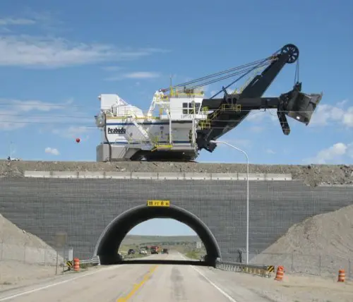
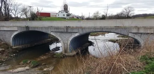
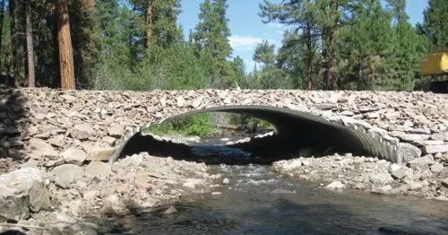
There is a flexible buried bridge option for just about any short- to medium-span crossing need. The most common applications have been bridges spanning across minor natural water courses. However, because of the aforementioned recent advances, flexible buried bridges also are becoming more common for grade separations (crossings where traffic passes through the bridge and over it), wildlife crossings (wildlife crossing over the bridge with traffic passing through it or vice versa), in-place bridge replacements (building a new buried bridge beneath an existing conventional bridge without detouring traffic), bridge replacements in remote areas, and other applications.
The advantages of using flexible buried bridges will vary based on project-specific considerations. However, the most-common benefits of using flexible buried bridges as an alternative to conventional bridges tend to be lower overall project cost, better fit based on site geometric limitations, constructability, speed of construction, and design advantages. Additional benefits may include but are not limited to:
• Site geometric limitations (road alignment, right of way, grading challenges, minimizing project footprint)
• Project location (remote area, congested urban area)
• Project schedule/material availability (need to accelerate material delivery or design-submittal process)
• Skill or experience of construction labor force (desire to use local or inhouse labor)
• Completed project cost
• Long-term maintenance and inspection cost
• Construction equipment requirements (lack of space for cranes or need to reduce equipment costs)
• Design challenges and considerations (heavy loads, load rating, seismic/settlement concerns, clearance requirements)
• Speed of construction (minimize traffic disruption and/or onsite construction time)
• Aesthetics (blend with surroundings, achieve a desired look)
• Resilience and environmental factors (ability to function after an extreme event such as seismic, flooding and damage; design for future needs; sustainability)
• Improved safety (no bridge deck to ice up, wider shoulders and walkways with potential to economically increase bridge width)
• Other unique, project-specific factors
An additional advantage gaining more attention given shrinking agency budgets is lower long-term inspection and maintenance costs. Flexible buried bridges consist of two basic bridge elements: the structure plates and connecting hardware (nuts and bolts). These structures eliminate bridge decks, which are a common maintenance challenge for bridge owners and expensive to rehabilitate. There are no bearings, joints, drains, abutments or other common bridge details that need to be regularly inspected or maintained. Inspection is simple, consisting of visual observations of the condition of the structure, spot measurements of the shape and general site observations. Maintenance on the interior may involve periodic cleaning and/or removal of silt or unwanted vegetation, depending on the application (grade separation vs. hydraulic crossing). At the road level, only routine pavement maintenance is required, which is far less expensive than bridge-deck repair.
Designing a Flexible Buried Bridge Structure
Evaluate Siting Conditions and Feasibility
The first step in developing a buried bridge alternative is to determine if site geometric limitations will allow a buried bridge structure to fit at the desired location. To evaluate this, it is critical to determine how large the structure needs to be and how much room is available. For hydraulic applications, the structure size typically is determined by a hydraulic analysis that establishes a minimum inside end area or span based on the water course passing through it. For non-hydraulic applications, the minimum structure size usually is determined based on inside clearance requirements.
Maximum structure size limitations often are governed by the available vertical distance from the bottom of the structure to the top of the road grade passing over the structure as well as minimum soil cover needed to meet design requirements. Other factors that limit structure size may include a minimum depth of soil cover needed for utilities crossing over the structure, the presence of existing bridge elements (for in-place bridge replacement applications), right-of-way boundaries, foundation depth and other project-specific geometric limitations.
As a rule of thumb, the maximum span-to-rise ratio for a flexible buried bridge is on the order of 4:1 to 5:1, depending on the structure span and shape. It is important to recognize that a buried bridge alternative will rarely have the same span as the conventional bridge option. This can help reduce the footprint of the project. Figure 5 illustrates basic information that should be considered when evaluating geometric feasibility.
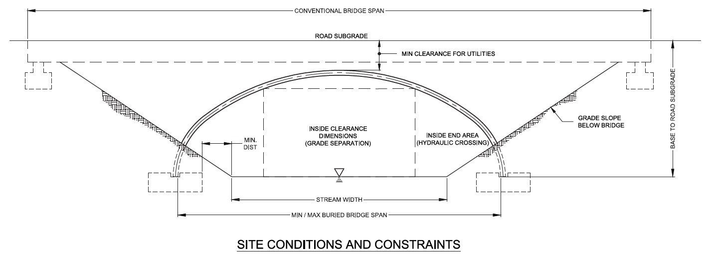
Engineers often approach a crossing by considering how long of a span is required to cross from “bank to bank.” However, many engineers have found that by reorienting the challenge to consider how large of an opening is required to pass the hydraulics or capture the clearance box can require a much smaller opening and span. Figure 5 effectively demonstrates how a buried bridge using a much smaller span and footprint can achieve the project objectives. This will typically result in a more cost-effective solution as well.
After feasibility of a buried bridge alternative is determined, the next step is to consider structure geometry options. At this point, the project engineer should reach out to a manufacturer to evaluate the best shape to use as a starting point for a design evaluation. Most structure manufacturers will have a library of “standard” shapes that can be used as a starting point, and one of these may be a perfect fit for what is needed. If not, a custom geometry can be developed that is optimized for the project requirements.
Basic Design Inputs
Buried bridge structures are designed in accordance with Section 12 of the AASHTO LRFD Bridge Design Specifications. The structure design evaluation will involve several basic inputs. Deep-corrugated buried bridge structures (corrugation depth >5”) are analyzed using finite-element analysis (FEA). In addition to the structure geometry and material properties, the FEA requires inputs for foundation soil properties, engineered backfill materials (placed around the structure), and site soil properties outside of the engineered backfill materials. The engineered backfill material is specified by the structure designer based on AASHTO requirements and the FEA results.
Foundation soil and site soil properties used for FEA inputs can usually be determined based on information provided in soil boring logs, test pit data and other information available regarding site conditions. If project soil information is limited or not available, reasonable assumptions can be made. When they are necessary, the assumptions should be clearly stated by the structure designer and acknowledged by the project engineer or owner. At this stage, assumptions may result in a conservative design. It would be in the owner’s best interest to obtain the needed soil information prior to final design to confirm the initial assumptions.
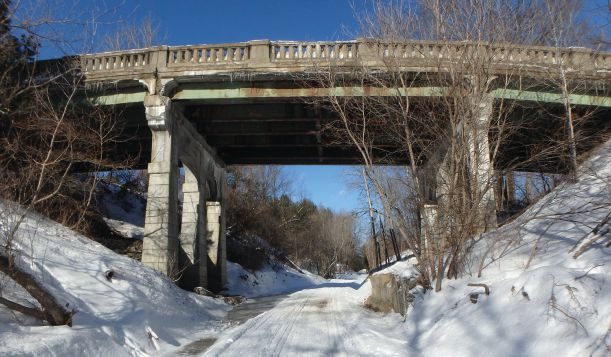

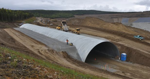
Figure 6. Before (top) and after (bottom) images of a bridge replacement with custom geometry. (Vermont Agency of Transportation; St. Johnsbury, Vt.)
Backfill Considerations
The AASHTO LRFD Bridge Design Specifications include requirements for minimum soil cover above the structure and the minimum width of engineered backfill on each side of the structure. The engineered backfill zone material is typically specified as a well-graded, angular, durable, coarse granular material with low fines. Although there may be some design flexibility based on the project application and structure size, engineered backfill zone materials will usually classify as A-1 or A-2-4 soils per AASHTO M145 (AASHTO soil classification standard). Fill material in contact with the structure will also need to fall within a range of desired electrochemical properties to achieve service-life requirements. These properties include (but may not be limited to) pH, resistivity, chlorides and sulfates. It is common to import quarried or processed material to satisfy the structural and electrochemical property requirements of the engineered backfill. However, if there is a desire to use site soils, geotechnical testing may be performed to determine if the onsite material is suitable.
Minimum cover and backfill zone width requirements are based on the structure geometry—specifically the ratio of crown radius to the haunch/side radius. The crown is the top of the structure, and haunch/side is the portion of the structure immediately adjacent to the crown that will usually have a tighter radius of curvature. If the radius ratio is greater than 5:1, the minimum soil cover allowed is 2 feet, and the minimum backfill zone width is 1/5 of the structure span. If the radius ratio is less than 5:1, the minimum soil cover allowed is 3 feet, and the backfill zone width is 1/3 of the structure span. For large-span structures, the minimum backfill zone width can be capped at 17 feet if the designer determines that width is acceptable based on the FEA results. The cost and availability of suitable engineered backfill zone material varies widely based on project location, local geology, regional usage and other factors. This can be a significant or a minor cost and should be considered when evaluating structure options.
Foundation Considerations
Foundation costs are a significant consideration for both conventional and flexible buried bridge options. Flexible buried bridges have a much-higher differential settlement tolerance than most conventional bridges and rigid structures. When the higher settlement tolerance is considered in the geotechnical analysis, a much-higher allowable bearing pressure often is possible, which can result in foundation cost savings or allow for use of spread footings when deep foundations otherwise would be needed.
The foundation-bearing elevation for buried bridges usually is much deeper than where a bridge sill would be located for a conventional bridge. In many cases, this allows for buried bridges to bear directly on a stable foundation soil layer, rather than needing to extend foundations deeper, carry out a soil-improvement program or use deep foundations that might be needed for a conventional bridge. It is important for the geotechnical engineer to consider foundation requirements for the buried bridge alternative differently than for the conventional bridge. In many cases, differences in foundation costs can be a significant deciding factor in the structure type.
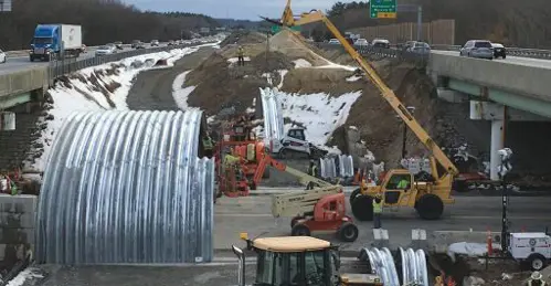
Construction Considerations
Construction costs and methods also should be considered and discussed with the manufacturer. Weights of individual plates typically are in the range of 350 to 1,200 pounds, depending on plate length and material thickness. This allows many structures to be assembled using a backhoe, forklift truck or other equipment already onsite for other work, keeping equipment costs down. A crane typically is not required for assembly, and there is no need for specialized labor or heavy equipment—many counties and general contractors prefer to use their own equipment and labor forces whenever possible. The modular nature of flexible buried bridges makes them ideal for staged construction. Part of the structure may be assembled and backfilled, and traffic put in service over the completed section while construction continues on the next.
Depending on site limitations, a new buried bridge can be built below an existing bridge without taking it out of service. Both scenarios (staged and in-place construction) can eliminate or significantly reduce the need for detours and traffic delays. Modular construction (where a buried bridge can be preassembled in large sections and set in place on the foundations) can be used in areas where only limited road closures are allowed. Each project has its own unique set of construction requirements and challenges, and those should be considered for each structure type. There can be significant differences in the time and construction effort required among the options being considered.
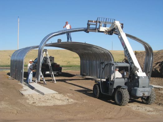
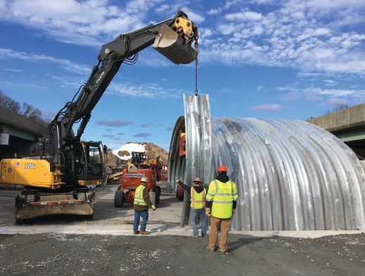
Figure 8. An assembly uses a backhoe (top) and forklift truck (bottom). (Attleboro, Mass., and Limon, Colo., respectively)

Conclusion
Flexible buried bridges can be an effective alternative to conventional bridges in many bridge applications. Project-specific requirements, limitations and design challenges will impact the feasibility of a buried bridge alternative, while factors such as site conditions, foundation alternatives, construction considerations and overall project cost can provide valuable data points to help make the best decision on the better bridge type for the project.
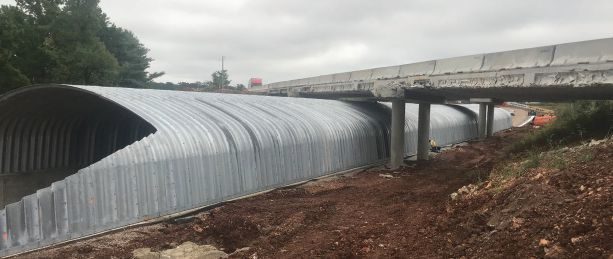
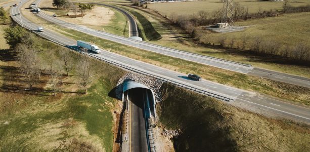
Figure 10. An in-place bridge replacement during construction (top) and finished (bottom).(Missouri DOT; Lawrence County, Mo.)
Joel Hahm, P.E., Contech Engineered Solutions; email: [email protected].
AASHTO LRFD Bridge Design Specifications (9th Edition, 2020)
AASHTO M145, Standard Specification for Classification of Soils and Soil-Aggregate Mixtures for Highway Construction Purposes
The Professional Development Series is a unique opportunity to earn continuing education credit by reading specially focused, sponsored articles in Informed Infrastructure.
If you read the following article, display your understanding of the stated learning objectives, and follow the simple instructions, you can fulfill a portion of your continuing education requirements at no cost to you. This article also is available online at v1-education.com.