The American Association of State Highway and Transportation Officials (AASHTO) Load and Resistance Factor Design (LRFD) Bridge Design Specifications (BDS), referred to throughout this paper as AASHTO BDS, has been the basis for design of all federally-funded highway projects since 2010 (References 1). The U.S. Department of Transportation’s Federal Highway Administration (FHWA) reports the practice of overly conservative settlement estimates with many foundation designs. These conservative estimates may lead to the unnecessary use of costly deep foundations or ground improvement. Many state-level transportation agencies have implemented an approach developed by the FHWA to explore the use of less-costly shallow spread footings based on a more realistic computation of immediate settlement. While this article provides an overview of the concepts recommended by the FHWA and focuses on bearing capacity, these concepts also can be applied to sliding.
FHWA recommendations
A 2010 report by the FHWA, Selection of Spread Footings on Soils to Support Highway Bridge Structures (References 7), cites the underuse of spread footings as the culmination of several factors. The FHWA identifies the following obstacles for designers:
- Limited knowledge or awareness of FHWA and AASHTO technical documents;
- Limited information from axial load tests and documented case histories;
- Use of overly conservative settlement estimates (i.e., settlement at nominal vertical displacement rather than initial or service settlement);
- Unrealistically low settlement tolerance specified (zero or 1/4 inch);
- Overestimated loads that cause potential settlement;
- Institutional culture and bias based on preference or traditional office standard operating procedure.
The end result, as concluded by the FHWA, is excessively conservative design processes that lead to costly deep foundation systems. Using a rational approach with AASHTO BDS Load and Resistance Factor Design methods enables substantial cost savings. In terms of 2009 dollars, the FHWA estimated that when practical, switching to shallow spread footings can save the public in excess of $180 million (References 5).
Some states report that where technically feasible, local construction markets favor the use of drilled shafts over spread footings due to competition and ground water conditions. Other states have provided documentation showing that the use of spread footings can reduce the foundation cost by at least 50 percent. (References 9)
Adoption of LRFD bridge design specifications by Departments of Transportation and other bridge and highway authorities provides an opportunity to revise “business as usual” analysis and design procedures. Implementation of LRFD design enables a rational approach to explore more cost-effective spread footings.
Many aspects of this topic are beyond the scope of this article and designers and engineers are strongly encouraged to review the references to use as their resource for detailed descriptions and recommended procedures (References 2, 4 and 8).
Geotechnical report
When the decision is made to design a spread footing, the structural engineer will need a geotechnical report from the geotechnical specialist. This report will have all the necessary information to begin the design, including determination of the factored soil bearing resistance and the settlement amount from the actual structural loads. However, the design is usually an iterative process, and after the footing is sized, the geotechnical specialist will need to verify the bearing capacity.
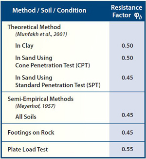
Table 1: Factors for Strength Limit States (AASHTO BDS, 2012)
Some pertinent terms that need to be defined are:
Nominal Bearing Resistance(qnn) — Unfactored bearing capacity of the soil, usually synonymous with the ultimate bearing capacity defined under Working Stress Design (WSD).
Resistance Factor (Φb)— In AASHTO BDS, Table 10.5.5.2.2-1 (Table 1) is used to determine factors for strength limit states, and range from 0.45 to 0.55 depending on the type of soil and the method for determining capacity. For the service limit state, resistance factor shall be taken as 1.0, except for overall stability, which is addressed in Chapter 11 of the AASHTO BDS. (References 1)
Factored Bearing Resistance (qr) — Nominal resistance multiplied by the resistance factor, used to check limit states; qr= Φb qnn
Note that this article uses notation similar to FHWA documents. Notation in the AASHTO BDS is slightly different, but the concepts are the same.
The geotechnical specialist should provide at least two of the above parameters; the third then can be calculated. Additionally, the geotechnical specialist will need to provide depth of footing embedment, taking into account any necessary scour requirements and frost penetration considerations.
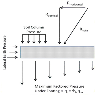
After a bearing resistance is provided, the structural engineer can estimate the footing size keeping in mind that bearing strength will not always be the controlling factor. Figure 1 presents a schematic of the typical forces the structural engineer should consider. In fact, settlement or sliding could control footing size. The determined footing dimensions need to be reported back to the geotechnical specialist to determine if the bearing resistance or settlement parameters change. This repetitive exercise may be time consuming, so the geotechnical specialist is better off providing bearing resisting charts that provide bearing resistance based on effective footing width. These charts also could include settlement considerations to streamline the process.
Figure 1: Schematic of typical spread footing - Forces and Pressures)
Limit states
The design process involves necessary checks of limit states of the foundation design. A limit state is defined simply as a “failure mode.” For spread footings, AASHTO BDS requires the following limit state checks:
Service Limit States — Shallow spread footings should be checked for serviceability of the foundation, and also the structure it supports. While having a high probability of occurring, issues such as settlement, horizontal movements, overall stability and scour usually are not life threatening. With larger footings, service limit states are the controlling factor in the footing design.
Strength Limit States — Strength limit states govern the design based on structural safety and the potential loss of load carrying capacity. Structural capacity of a foundation is designed at this limit state using factored loads. Bearing capacity, limiting eccentricity (overturning), excessive loss of contact and sliding are checked at this limit state.
Extreme Event Limit States — AASHTO BDS defines the extreme event as a major environmental event. Although rare, these events include flooding, seismic activity and high winds, as well as situational occurrences such as vessel or vehicle collision, and other site-specific situations.
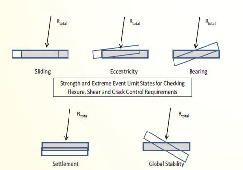
Figure 2 depicts the most common displacements relative to the limit states.
Figure 2: Checking flexure, shear and crack control for Limit States
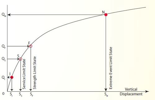
Again, for larger spread footings, the serviceability of the footing frequently controls. Tolerable settlement criteria should not be based on a structure that is in the final design state, as if a bridge was placed on the site all at once as a whole, completed structure. As a footing is constructed, some settlement will occur; as the next structure component is constructed, some additional settlement will occur, and so on. If the settlements during construction can be tolerated, it is likely that only the final settlement of the superstructure placement will have to be considered. The relationship between allowable or tolerable settlement and the corresponding bearing is shown in Figure 3.
Factored bearing resistance chart
Buried soil-interaction arches typically have shallow spread footing dimensions where the effective length to effective width ratio (L’f/B’f) is greater than 10. As such, the shallow spread footing is classified as “continuous” and the FHWA sets the depth of significant influence (DOSI) to be four times B’f. The DOSI is the thickness of soil that compresses, thus causing immediate settlement.
If the footing is subject to only vertical load from the arch reaction (V), then the effective width (B’f) is the same as the physical width (Bf). If there is any eccentricity (e) at the top of the footing, then effective width is computed considering the combination of vertical resultant load and moment (M):

Figure 3: Typical axial load versus vertical displacement curve to illustrate Limit States (FHWA 2010 - References 7)
Calculation of total settlement as the sum of immediate and long-term settlement is a necessary exercise to study the effects on the structure. The FHWA recommends using the immediate settlement analysis described by Schmertmann (References 3) rather than the conservative method used in AASHTO BDS. In addition, the FHWA recommends considering vertical settlement of up to 4 inches. For typical span lengths, this recommended amount of settlement exceeds the tolerable differential settlement for soil-interaction arches as measured across the legs of the arch. While the soil-interaction structure likely will not suffer, the designer still should consider if the settlement will affect the functionality of features such as approach slabs, surface drainage, retaining walls or utility lines.
Using the LRFD approach, settlement usually controls the design of spread footings. The factored net bearing resistance of a shallow spread footing is the lesser of:
Strength Limit State — Applied stress that is equal to net nominal bearing resistance (qnn) multiplied by the resistance factor (Φb) or, qr= Φb qnn
Service Limit State — Applied stress that results in the specified amount of settlement (Stol). The maximum toleable settlement should be determined by structural requirements or engineering judgment.
Figure 4: Hypothetical factored bearing resistance chart, based on FHWA 2010 (References 7)
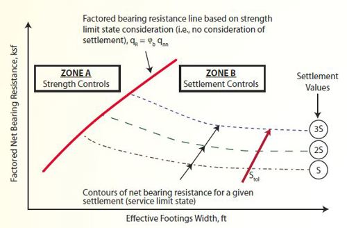
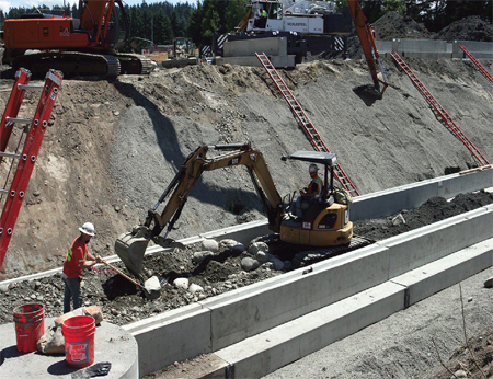
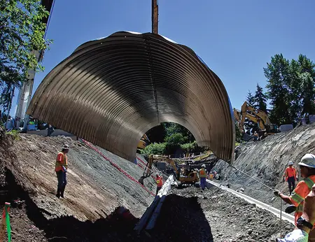
Referring to Figure 4, relatively narrow footings will be controlled by strength. However, from a practical perspective, most spread footings will be wider and thus controlled by settlement. Recall that the DOSI is four times deeper than the footing is wide. The only way to satisfy the settlement limit (Stol) is to reduce the applied stress. The settlement- controlled behavior sets up the important relationship of decreasing factored bearing resistance with increasing footing width. Factored bearing resistance charts provide important information to help clarify the interrelationship between B’f , qr and (Stol). The chart also provides intuitive insight on the most cost-effective footing width as a function of (Stol). Shallow spread footings require significantly less time to excavate and place than deep foundations consisting of drilled or driven piles. Shallow spread footings commonly are constructed using cast-in-place methods. Precast spread footings and newer hybrid systems that combine the installation of speed of precast with the economy of cast-in-place also are available (Photos 1 and 2).
Precast units are fabricated offsite in a factory controlled environment, and then shipped to the project controlled environment, and then shipped to the project site. Consistent with the FHWA “Every Day Counts” initiative for Accelerated Bridge Construction, foundations are constructed concurrently with the site work. This enables contractors to reduce overall project time since the work is completed faster. The combined result of efficient design and speedier construction is a more economical solution for owners while placing fewer burdens on public funding.
|
Photo 1: Precast, pedestal spread footings for a fish passage culvert
(Washington State DOT, 2011))
 |
|
Photo 2: Structural plate arch positioned on precast pedestal spread footings (Washington State DOT, 2011)
 |
Additional Considerations Regarding Scour and Frost Depth
Scour
Erosion near the bottom of a foundation may be caused by increased flow due to long-term changes to the watershed as a result of natural or man-made processes, such as urban development, dam construction or logging operations. It may also result from the cutting of the soil by constricting the channel though a culvert and increasing the flow velocity.
The basic mechanism is that the water flow velocity is sufficient to dislodge soil particles and create undesired voids. Foundations either may be designed to address scour or additional features may be used to mitigate the effects of scour. Design considerations may consist of using a full invert or slab foundation, over-excavating erodible soil and replacing with more competent soil, lowering foundations to more suitable soil or bearing foundations on rock.
The designer should consider the cost of increased depth of excavation against possible changes in the factored bearing capacity at that depth. As an alternate to excavating below scour depth, scour mitigation strategies such as the use of articulated concrete block (References 6), erosion control fabrics or mats, channelizing flow using sheet piling or placing rip rap around foundations could be considered. The evaluation of scour potential for a given site is beyond the scope of this article and the reader is encouraged to review reference materials for further guidance and best practices.
Frost Depth
In cold climates with frost susceptible soils, the development of ice lenses can result in uplift and possible damage to concrete foundations. Building codes generally require the minimum depth of a foundation to be lower than the frost line. Bridge structures founded on soils that are not susceptible to frost can normally tolerate more movement than a building. Buried arch structures, especially flexible metal culverts, withstand minor footing movements without detrimental effects.
From an engineering perspective, the highway structure foundation does not have to extend below the frost line. If the foundation soil is determined to be frost susceptible, it is good practice to over-excavate and replace with a free-draining soil. In general, soils that retain water and promote capillary action such as clays, silts and fine sands are more susceptible to frost than coarse sands and gravels.
Summary
This article presents the FWHA recommendations for using shallow spread footings in lieu of deep foundations where technically feasible. The material presented is a brief overview and the reader is encouraged to learn more through using the reference documents cited. The documents include complete step-by-step methods for computing settlement estimates and performing full designs for shallow spread footings.
Jim Riseborough, P.E.,is a Senior Structural Engineer with Contech Engineered Solutions and specializes in precast concrete, buried arches and foundations. He has 13 years of experience with design of buildings, bridges and other infrastructure.
Steve Tysl, P.E,is a Senior Design Engineer with Contech Engineered Solutions and specializes in buried corrugated metal arches and culverts. A member of ASTM and SEAoO, he has 21 years of experience in civil engineering, geomechanics, construction materials and construction management.
REFERENCES
American Association of State Highway and Transportation Officials (AASHTO):
- American Association of State Highway and Transportation Officials, AASHTO LRFD Bridge Design Specifications, 2012.
- American Society of Civil Engineers, S.O. Akbas and F.H. Kulhawy, “Axial Compression of Footings on Cohesionless Soils. I: Load-Settlement Behavior,” Journal of Geotechnical and Geoenvironmental Engineering, Vol. 135, No. 11, pp. 1562-1574, 2009.
- American Society of Civil Engineers, J. H. Schmertmann, J.P. Hartman and P.R. Brown, “Improved Strain Influence Factor Diagrams,” Journal of the Geotechnical Engineering Division, Vol. 104, No. GT8, pp. 1131-1135, 1978.
- Federal Highway Administration, Ryan R. Berg, P.E., with V. Elias, J. Welsh, J. Warren, R. Lukas and G. Collin, Ground Improvement Methods Reference Manual – Volume I, FHWA-NHI-06-019, Volume II, FHWA-NHI-06-020, August 2006.
- Federal Highway Administration, J.L. Briaud and R. Gibbens, Large-Scale Load Tests and Database of Spread Footings on Sand, FHWA-RD-97-0680, November 1997.
- Federal Highway Administration, F.P. Lagasse, L.W. Zevenbergen, J.D. Schall and P.E. Clopper, “Bridge Scour and Stream Instability Countermeasures,” Hydraulic Engineering Circular No. 23, FHWA-NHI-01-003/HEC-23, March 2001.
- Federal Highway Administration, Naresh C. Samtani, P.E., Ph.D., Edward A. Nowatzki, P.E., Ph.D., and Dennis R. Mertz, P.E., Ph.D., Selection of Spread Footings on Soils to Support Highway Bridge Structures, FHWA-RC/TD-10-001, February 2010.
- Federal Highway Administration, Naresh C. Samtani, P.E., Ph.D., and Edward A. Nowatzki, P.E., Ph.D., Soils and Foundations Reference Manual – Volume I, FHWA-NHI-06-088, Volume II, FHWA-NHI-06-089, December 2006.
- Ohio Department of Transportation Office of Research and Development and the FHWA from Ohio University ORITE, Shad Sargand and Teruhisa Masada, Further Use of Spread Footing Foundation for Highway Bridges, FHWA-OH-2006/8, April 2006.

