In 1896, an apparently cost-conscious Indiana county engineer conceived an alternative to the bulky masonry, iron, and timber drainage structures then used as roadway cross drains. His revolutionary idea involved forming corrugated steel sheets into circular pipe. After several years of development, these new steel culverts demonstrated that lightweight pipe in longer lengths resulted in easier, faster, and more economical construction. With later development of corrosion-resistant steels and protective coatings to extend service life, combined with the introduction of corrugated aluminum pipe, this unique genre of roadway culvert quickly advanced into mainstream construction. During the 1960s, thermoplastic pipes began to vie for a place in the roadway drainage market, and several types high-density polyethylene (HDPE) and polyvinyl chloride (PVC) pipes are currently used as culverts and other drainage structures.
Beginning of flexible pipe research
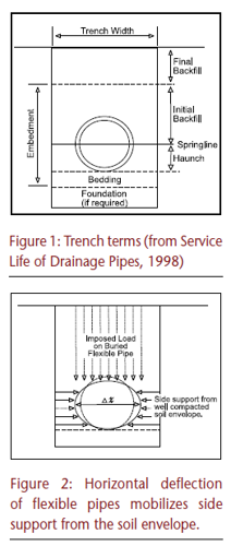
Field studies, conducted for several decades after the introduction of corrugated steel drainage pipe, revealed that the new steel culverts were remarkably free of the usual structural defects — such as cracking — associated with iron and concrete pipes. To develop a better understanding of the performance of buried corrugated steel pipe, independent culvert load research was performed at several universities well known for their soils engineering departments. While identifying the differences between rigid and flexible pipes, it was discovered that "… flexible corrugated metal pipe deflected slightly under imposed loads, and because of this it carried less weight from the fill than that coming on rigid types. Because of this deflection, side support was developed which distributed the pressure uniformly around the corrugated pipe instead of concentrating it at the top and bottom as was the case with rigid pipe." (Armco, 1960)
Iowa State College (now Iowa State University of Science and Technology), one of the participants in the aforementioned research, developed a design model that related applied loads from soil coverings (dead loads) and intermittent loadings from vehicles (live loads from moving autos, trucks, or trains) to the stability of flexible pipes in various soil conditions. This model for designing buried flexible pipes — which were mostly manufactured from steel — was used extensively by the engineering community for many years.
Flexible pipe design basics
The Iowa State College criteria attributed the stability of buried flexible pipe to a combination of soil and pipe stiffness. Pipe stiffness is a product of material properties and pipe wall profile geometry (elastic modulus and moment of inertia, respectively), whereas soil stiffness depends upon soil type and procedures used in placing it as an embedment. The general relationship is expressed as:
(Equation 1)
Pipe Deflection= Load/Pipe Stiffness+ Soil Stiffness)
Quantifying side soil stiffness, along with establishing these as soil-structure composite systems, were perhaps the most significant outcomes of the Iowa studies. Recognizing soil stiffness — or passive resistance — as essential for predicting the structural stability of buried flexible structures was a major step in establishing appropriate design procedures.
Although some thermoplastic materials were used in other applications prior to their introduction to the drainage market, these structures were perhaps the first subjected to long-term sustained loadings and where the size of the product was relatively large. As the use of flexible plastic pipes — especially those with corrugated wall profiles — increased, evidence gathered to show that the existing design approach for steel pipes was inapplicable for predicting their long-term behavior. This led to a newer approach concentrating on the structural capabilities of the pipe wall within a soil-structure composite wherein, based upon a stiff soil envelope, wall strength and wall profile stability are the limiting design criteria. The corresponding design procedures for buried flexible pipes are usually governed by American Association of State Highway and Transportation Officials (AASHTO) Load and Resistance Factor Design (LRFD) Bridge Design Specifications, Section 12.
Pipe wall factors
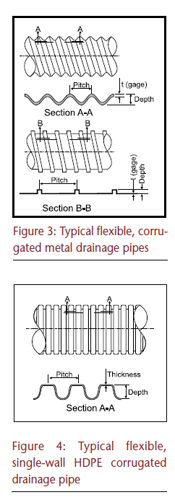
In addition to the different mechanical properties (discussed later) between thermoplastic materials and metal, variations in wall geometry must be factored into the design process — especially for plastic pipes, for which considerable differences exist between manufacturers. While corrugated steel pipe wall configurations (Figure 3) are standardized within the industry, such standardization has yet to be realized for plastic pipes.
Although AASHTO specifications make general allowances for these variations, designers are strongly advised to evaluate data from various candidate suppliers to determine product-specific properties accurately for comparison with those provided by AASHTO. Using the actual pipe wall properties from a specific source helps ensure a correct analysis about load-carrying capabilities. Figure 4 illustrates a typical corrugated HDPE drainage pipe.
Soil factors
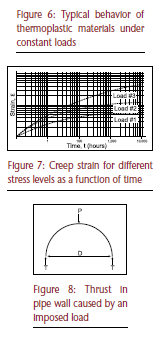
Flexible pipes redirect applied forces from earth and vehicle loads to adjacent soils. Thus, a relatively stiff and unyielding side soil helps stabilize the buried pipe, which is the essence of flexible pipe design; they are composite structures comprising an elastic material (in this case, a circular pipe) and a soil envelope, with each material influencing the structural design.
Derived from earlier Iowa studies, soil stiffness is defined as the modulus of passive resistance of the soil envelope and is often simply referred to as the factor E'. This factor, empirically derived from numerous tests, is a function of the type of soil and its placement as an embedment. For example, a well-graded granular soil with little or no plasticity (less susceptible to permanent deformation) compacted during placement to a high percentage — say 90 percent — of its native density will provide an E' value approaching 2,000 pounds per square inch (psi). An ideal embedment material would consist of well-graded gravel or gravel/sand mixtures with little or no fine particles (0.075 mm and smaller) compacted to 95 percent or higher density to produce E' values approaching 3,000 psi. On the low end, high-plasticity clay soils with a high percentage of fines are very elastic and completely unsuitable as an embedment material because they permanently deform and have virtually no stiffness properties.
Steel elasticity and recovery
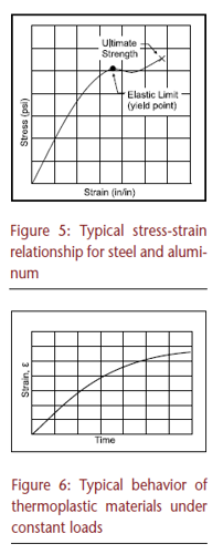
Virtually all initial design procedures for flexible pipes evolved from experiences with buried steel pipes typically manufactured from relatively light gage corrugated sheets. Metals most commonly used to manufacture drainage pipes provide a high degree of predictability with respect to their response to applied forces. Their relatively linear relationship between strain (deformation) and stress (load) is evidenced by a constant modulus of elasticity, this property being crucial to the structural design since it represents the predicted behavior of materials under load. Figure 5 illustrates the well-known stress strain relationship for metals, in which the virtually linear relationship between stress (load) and strain (deformation) continues until reaching a threshold known as the yield point. This point represents the elastic limit, after which permanent deformation occurs. Until reaching the yield point, removing the load results in a return to its initial shape regardless of the load's duration.
Plastic pipe's elastic performance
The primary idiosyncrasy differentiating thermoplastics from metal in structural applications is their different response to long-term stress. Materials classified as "elastic" (such as that in Figure 5) deform under stress in direct proportion to the applied load but return immediately to their original state when the load is removed unless the elastic limit has been exceeded. Thermoplastic materials, on the other hand, respond differently under loading conditions by experiencing further deformation even when the force remains constant (Figure 6). This relatively complex phenomenon, known as creep deformation, is the result of "fluidity" within the molecular structure whereby molecular rearrangement occurs within the material. This property is generally termed viscoelasticity — an amalgamation of the words "viscous" and "elasticity." The different stress-strain correlation for thermoplastics precludes the determination of a specific elastic modulus (E) in the same manner as truly elastic materials.
Progressive deformation of a thermoplastic subjected to loading conditions, however, causes a redistribution of stresses (called stress relaxation), and a point occurs in time when the deformation rate becomes relatively stable. This point is usually identified by applying different constant loads to the product (flexible plastic pipe, in this case) and observing the strain (deformation) over a period of at least 10,000 hours.
As shown in Figure 7, the strain rate will usually stabilize shortly before the 10,000-hour limit. Based on data extrapolated from such tests, an elastic modulus can be calculated to predict stability for a 50-year time period. This modulus, sometimes referred to as the creep or flex modulus, differs for each type of thermoplastic, such as PVC or HDPE, and their various grades (cell classifications). The 50-year elastic modulus is always substantially less than the short-term elastic modulus established by basic tension tests or simple parallel plate load tests (ASTM D2412) performed for production quality control purposes. A common parallel plate test determines stiffness within limited conditions, such as deflection induced by plates moving at a fixed rate of ½ inch per minute for several minutes. Since such loading conditions do not simulate many actual installations or buried pipe conditions, the more enlightening 10,000-hour load test and stiffness testing at installation temperatures are required for developing a better correlation with actual field conditions. Since the modulus (E) of any material is the ratio of stress to strain, the 50-year modulus for thermoplastics is aptly defined as the applied uniform stress divided by the accumulated 50-year strain, or creep (ASTM D638).
Because the strength and stiffness properties of thermoplastics — such as HDPE and PVC — are time, rate, and temperature sensitive, the stiffness obtained from laboratory tests via controlled parallel plate tests do not necessarily provide the stiffness values appropriate for design. For instance, thermoplastics are more pliable and less stiff at elevated temperatures, and pipe deflected quickly exhibits a greater stiffness than when deflected slowly.
Because of this unconventional behavior, AASHTO standard specifications apply an 80-percent reduction factor to the initial modulus to obtain the 50-year elastic modulus for designing buried corrugated HDPE pipes, which represent most of the thermoplastic pipe used for roadway culverts and other drainage applications,
Design fundamentals
For many years, AASHTO design procedures analyzing the structural adequacy of buried plastic pipes generally conformed to the principles for light gage steel structures — appropriately modified for thermoplastic pipe alternatives — so that pipe wall stresses were used to evaluate its behavior in the presence of anticipated loads. More recently, however, AASHTO and others have embraced the newer — yet more complex — LRFD analytical procedures. While it is generally conceded that LRFD designs have advantages compared with previous models, it is beyond the scope of this article to delve into the design of buried pipes using LRFD criteria. Nonetheless, it can be instructive to cover the design fundamentals using the relatively uncomplicated procedures in prior AASHTO specifications, such as AASHTO Standard Specification for Highway Bridges Section 12: Soil-Corrugated Metal Structure Interaction Systems, and AASHTO Standard Specification for Highway Bridges Section 17: Soil-Thermoplastic Pipe Interaction Systems, these two being the immediate forerunners of current AASHTO specifications. such as AASHTO Standard Specification for Highway Bridges Section 12: Soil-Corrugated Metal Structure Interaction Systems, and AASHTO Standard Specification for Highway Bridges Section 17: Soil-Thermoplastic Pipe Interaction Systems, these two being the immediate forerunners of current AASHTO specifications.
The typical analysis begins with determining the thrust (stress) in the pipe wall:
Equation 2:
T = P (D/2)
In which:
T = thrust (pounds per foot);
P = design load (pounds per square foot); and
D = pipe diameter (feet)
The force calculated in Equation 2 must be resisted by the pipe wall section (Figures 3 and 4, Section A-A or Section B-B). Therefore, an initial pipe wall cross-section is determined from the following:
Equation 3:
A = T/Ys
In which:
A = minimum area of the pipe wall section (square inches per
foot);
T = thrust (pounds per foot); and
Ys = design yield point (psi) for metal or the long-term
(50-year) ultimate rupture strength for plastics.
The preliminary wall cross sectional area becomes the starting point for the remaining design procedures, and standard wall areas are available from tables in the appropriate AASHTO specification. Select one that is nearest to the minimum area and calculate the pipe wall stress as follows:
Equation 4:
Sw = T/A
In which:
Sw = pipe wall stress (psi);
A = minimum area of the pipe wall section (square inches per foot);
T = thrust (pounds per foot).
When designing metal and thermoplastic flexible pipes using AASHTO specifications, different procedures are required to determine the critical pipe wall stress for steel and HDPE flexible pipe materials that basically reflect the atypical — compared to metals — long-term stress-strain behavior of thermoplastics. Additionally, these methods are based on flexible pipe installed so that the supporting side soil stabilizes the system so that the pipe wall performs as a fixed compression member, making the soil modulus (E') a factor that affects the critical (allowable) pipe wall stresses because it restricts lateral bending. Because E' is a vital part of the composite structural design, AASHTO is specific about the minimum requirements for soil embedment, generally limiting the types of backfill/embedment to granular materials with little or no plasticity and no organic materials, compacted to at least 90 percent standard density. AASHTO also sets limitations on trench dimensions to ensure good backfill placement and compaction.
The pipe in question must also be checked for wall buckling using the following methodology.
Equation 5:
If S<(r/k)(24 E/fu)1/2, then fcr = fu - (fu 2/48E ) (k s/r)2
Equation 6:
If S > (r/k)(24 E/fu)1/2, then fcr=(12E )/(k s/r)2
In which:
r = radius of gyration of corrugated pipe wall (inches);
k = soil stiffness factor, 0.22;
E = modulus of elasticity of pipe material (psi);
S = pipe diameter, or span in inches;
fu = specified minimum tensile strength (psi); and
fcr = critical wall stress, (psi)
Note, the values of r, E and fu are listed in the appropriate AASHTO standard specification.
Now, compare the pipe wall stress (Sw) calculated in Equation 4 to the critical pipe wall stress from Equation 5 or 6. If the critical pipe wall stress is less than Sw , the pipe wall area resulting from Equation 4 is insufficient and the series of calculations are repeated until a satisfactory result is obtained by increasing the wall area.
Wall stresses in thermoplastic drainage pipe
The analysis of buried flexible thermoplastic pipes is similar to that for corrugated steel pipes except that the process for determining the critical pipe wall stress has been modified to account for the long-term viscoelastic behavior, the subsequently reduced working stresses of thermoplastic, and its greater reliance on support from the soil envelope. Beginning with the selected pipe wall profile and resulting effective area for the required pipe diameter, calculate the critical buckling stress of the pipe wall as follows:
Equation 7:
fcr = 9.24(R/A)(BMsEI/0.149R3)1/2
In which:
fcr = critical wall stress (psi);
R = effective radius (inches) = c + ID/2 (Values for c, the distance
from the inside surface to the neutral axis, are available from
AASHTO tables or manufacturer's data);
A = area of pipe wall (square inches per foot);
B = water buoyancy factor (1 - 0.33hw/h), where hw = height
of water above top of pipe (feet) and h = height of ground
surface above top of pipe (feet);
Ms = E' = soil modulus (psi) = 1,700 for side fills meeting the
criteria in the appropriate AASHTO standard specification;
E = long-term (50-year) modulus of elasticity of
the plastic (psi);
fu = specified minimum ultimate tensile strength
(psi);
ID = Pipe inside diameter in inches; and
I = moment of inertia per unit length of cross section of the
pipe wall (inches4/inch).
Note: A buoyancy factor is required because HDPE has a specific gravity of approximately 0.955 and may float in wet conditions. The values of c, ID, A, and E (50-year modulus) are listed in the appropriate AASHTO standard specification.
The pipe wall area, A, used thus far is the total area of the pipe wall cross-section per linear foot of plastic pipe. In some cases, it has been noted that this overstates the results because not all elements of the wall profile contribute equally to the structural capacity of the member. Consequently, in more recent AASHTO specifications, an "effective" wall area is used instead. Because the wall profiles (ribs or corrugations) for metal pipes are standardized, AASHTO and other design specifications list the net effective properties for design directly, thereby eliminating the need to calculate the net effective design properties for the AASHTO LRFD Bridge Design Specifications.
Live and dead loads
As a matter of simplification, the applied loads in the foregoing analyses are those related only to the soil overburden — commonly known as the "dead load" — and the applicable elastic modulus for plastic pipes is its long-term (50-year) strength. When plastic pipes are subjected to dynamic loading conditions, such as those from moving vehicles on surface roads above the pipe, the short-term or initial modulus may be used because the live-load duration is brief. AASHTO provides both initial and long-term thermoplastic properties for design.
Managing installation forces
Once the structural analysis is satisfactorily concluded, it remains to determine how the selected pipe is likely to resist the various forces imposed during handling and installation. The most common measure of "handling rigidity" is termed the flexibility factor (FF), which is determined by:
Equation 8:
FF = D2/EI
In which:
FF = flexibility factor (inches per pound);
D = pipe diameter (inches);
E = modulus of elasticity of pipe material (psi); and
I = moment of inertia per unit length of cross section of the
pipe wall (inches4/inch).
Note: AASHTO standards for buried corrugated metal structures list the values of I for all commonly available pipe wall profiles.
The flexibility factor helps establish minimum pipe stiffness requirements for practical handling and installation without undue care or bracing. The various criteria have been established through experience, and lower values from Equation 8 indicate higher degrees of stiffness. Pipes manufactured from different materials or with different wall configurations will have discrete allowable flexibility factors, which are listed in the relevant AASHTO specification.
Summary
Flexible pipe provides many advantages compared with pipe manufactured from rigid materials, most significantly its ability to draw upon the strength of the adjacent soil to readily withstand deep burial without experiencing wall collapse. Because of the composite soil-pipe interaction, flexible pipe design procedures are vastly different than those for rigid pipes such as concrete, iron, and clay. Understanding how the flexible pipe relates to its neighboring soil — thereby establishing a functional pipe-soil composite structure — is key to a successful design (Gabriel, 1998).
The addition of thermoplastic flexible pipe with different long-term strength characteristics has resulted in design criteria specific to that material. Although capable of serving as an alternate to corrugated steel pipe, thermoplastic pipes cannot share the same design procedures because of their unconventional response to sustained loading conditions. As plastics of all kinds find their way into various aspects of civil construction, engineers must expand their awareness of how these differ from traditional materials and apply the most appropriate design methods to ensure proper application.
Jim Noll, P.E., is director of engineering services for CONTECH Construction Products Inc. He has 30 years experience in the corrugated metal pipe industry and is an active member of various technical organizations, including ASCE, AREMA, and ASTM.
REFERENCES
- AASHTO, 2002, Standard Specification for Highway Bridges, 17th Edition, Section 12 Soil-Corrugated Metal Structure Interaction Systems
- AASHTO, 2007, LRFD Bridge Design Specifications, 4th Edition, Section 12 Buried Structures and Tunnel Liners
- AASHTO T 180 Standard Method of Test for Moisture-Density Relations of Soils Using a 4.54-kg (10-lb) Rammer and a 457-mm (18-in.) Drop
- ASTM A-796 Standard Practice for Corrugated Steel Pipe, Pipe-Arches and Arches for Storm and Sanitary Sewers and Other Buried Applications
- ASTM A-798 Standard Practice for Installing Factory-Made Corrugated Steel Pipe for Sewers and Other Applications
- ASTM A-998 Standard Practice for Structural Design of Reinforcements for Fittings in Factory-Made Corrugated Steel Pipe for Sewers and Other Applications
- NCSPA Installation Manual for Corrugated Steel Pipe, Pipe Arches, Structural Plate
- NCSPA, 1999, Design Data Sheet No. 18A
- NCSPA, 2008, Corrugated Steel Pipe Design Manual, First Edition