Introduction To Designing Corrugated Metal Pipe (CMP) Stormwater Detention Systems
By Gabe Weaver, P.E. and Pat Valentine, EIT
Published: May 2017
Overview
The two essential functions of a stormwater management system are to control the 1) quality and 2) quantity of runoff leaving a site. There are various ways to do this; a common method is with an aboveground system in the form of a detention pond, but these take up usable land space. This is not a major issue in rural areas, but in urban environments, land space is expensive, and a loss of land space results in lost revenue.
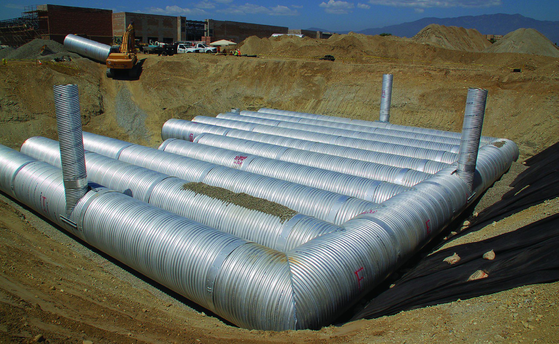
As a result, engineers and developers often turn to underground solutions, which take many forms. One of the most common is an underground detention system made from corrugated metal pipe (CMP). These systems are employed on a site to reduce the quantity of stormwater runoff leaving a site by temporarily storing the runoff that exceeds a site’s allowable discharge rate and releasing it slowly over time.
Designing CMP detention systems is a complex task. This article is not intended to be a complete design guide; it is intended to address three questions engineers often have regarding designing CMP detention systems:
1. What is the value of placing a system underground?
2. How can CMP systems be designed and configured to provide the most economical solution?
3. What are the top design “red flags” that engineers should be aware of?
The Value of Going Underground
The use of land space for an aboveground detention pond in urban environments often can result in lost revenue for the owner. The question then becomes how to quantify the value of putting the pond underground in a detention system. One method is to calculate the value of additional leasing space gained if a pond is placed underground, allowing the developer to maximize their return on investment by using all available land space. Consider the following example:
A typical parking space is 9 feet by 18 feet: 162 square feet. For every 1,000 square feet of developed space, regulations typically require 2.6 parking spots. In other words, 1,000 square feet of developed space requires 421.2 square feet for parking. The more developed space you have, the more parking spaces you need. You just need to ensure the amount of developed space plus the amount of parking space does not exceed the lot size.
Consider a parcel that has two, one-acre ponds. One developer may look at the parcel and decide they could never maximize the return on investment, as they can’t fully use all the land space. Another developer could look at the same parcel and see it as a great opportunity. Those two ponds represent 87,120 square feet of footprint.
By putting the detention system underground, the second developer will have an additional 87,120 square feet for parking, which will allow for an additional 206,000 square feet of office space. With office rates ranging from $13-$23 per square foot annualized, this represents $2.7-$4.7 million of additional revenue. Extrapolated over a 10-year timeframe, the developer could make an additional $25-$50 million. In areas such as New York City and San Francisco, the return will be even higher, with rates ranging from $65-$74 per square foot.
Owners, developers and engineers all can benefit by exploring the use of below-ground stormwater detention systems to maximize land space, which maximizes revenue.
Cost-Effective Design and Layout
To minimize cost, the three most-important goals should be to 1) shrink the footprint of the system by maximizing storage volume within a given area, 2) eliminate unnecessary welding/fabrication and 3) eliminate unnecessary structures.
Shrinking the Footprint
The goal of any CMP detention system should be to maximize the vertical space available to minimize the overall footprint and thereby reduce material, excavation and backfill costs. To do this, it’s recommended to use the largest-diameter pipe possible.
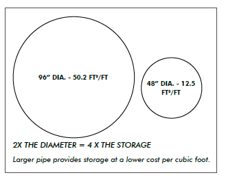
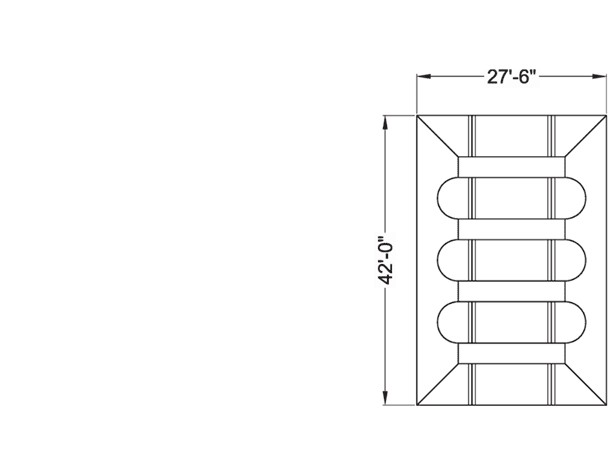
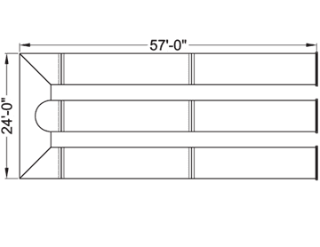
Figure 1 – Storage Capacity of Larger Pipe
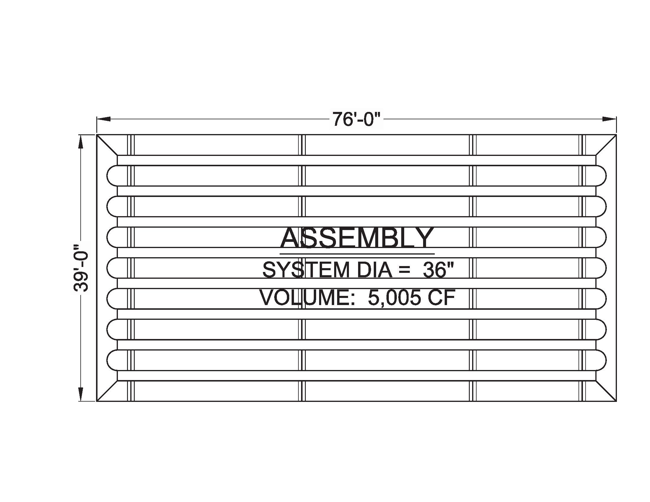
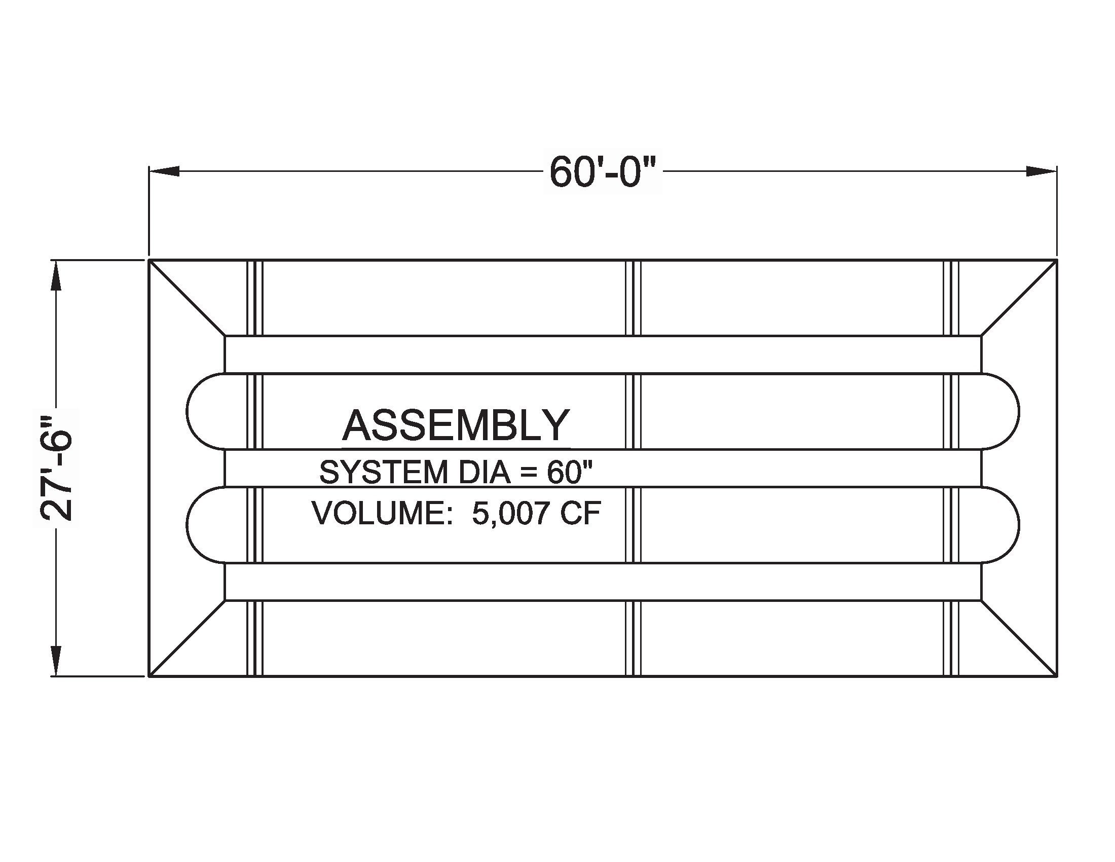
Shrinking the Footprint System 1, Non-Optimized System Results In Larger FootprintShrinking the Footprint System 2, Optimized System Reduces Footprint
Increasing the depth of a CMP detention system allows for a smaller footprint while storing the same amount of water. As shown in Figure 1, doubling the diameter of pipe yields four times as much storage volume per foot in the pipe. This provides significant cost savings per cubic foot of storage. Also, more vertical storage space means a smaller footprint, equating to less excavation, less backfill and lower project costs. Consider the following example:
System 1 is made from 36-inch-diameter pipe that provides 5,007 cubic feet of storage. System 2 is made from 60-inch-diameter pipe that provides the same 5,007 cubic feet of storage. Both systems provide the same amount of storage, but System 2 is the most-economical design as it reduces material, fabrication, excavation and backfill costs. Having fewer runs of pipe will cut down on the number of welds and special fabrication requirements. Having fewer welds also will cut down on lead times. In addition, System 2 has a footprint that’s 1,300 square feet smaller than System 1, reducing excavation and backfill costs. The only instance where System 2 may not be the best option is if you don’t have the available depth for the larger-diameter pipe.
Eliminating Unnecessary Welds
The rule of thumb is to use as much straight pipe as possible to reduce the number of tees and elbows in a design. Doing so will result in a more cost effective and efficient design as well as reduce lead times. In the example below, both systems are designed with 72-inch-diameter pipe and roughly the same storage volume. System 3 uses only two elbows and one tee and will be much more cost effective than System 4, which uses four elbows and six tees.
Eliminating Welds System 1, Non-Optimized System Due To Large Number of Welds
Eliminating Welds System 2, Optimized System Due To Reduced Number of Welds
Eliminating Unnecessary Structures
Costs also can be reduced by eliminating concrete structures such as catch basins and outlet-control structures by incorporating them into the CMP system. For example, a riser with a grated inlet can be added to a system at the low point of a parking lot to eliminate a concrete catch basin. Internal weir plates and multiple external outlet stubs often can be used to eliminate a separate concrete outlet-control structure downstream. CMP’s ability for custom fabrication allows engineers to be creative and design customized systems to meet site-specific conditions that will benefit clients in terms of functionality and reduce costs.
CMP Detention Systems in Corrosive Environments
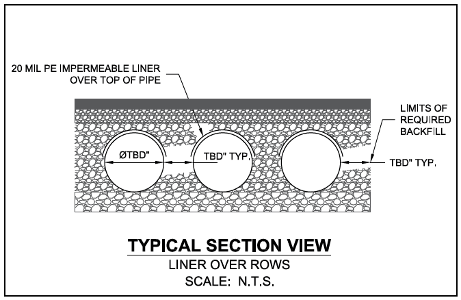
CMP is available in various coatings for a variety of recommended environmental pH and resistivity ranges. A site’s resistivity may change through time when various types of salting agents are used, such as road salts for deicing purposes. If salting agents are used on or near a project site, a geomembrane barrier is recommended with the system. The geomembrane liner is intended to help protect the system from the potential adverse effects that may result from the use of such salting agents, including premature corrosion and reduced service life.
The project’s Engineer of Record is to evaluate whether salting agents will be used on or near the project site and use his or her best judgment to determine the appropriate geomembrane details for the system. Below is an example detail that may be applicable for such situations:
Design ‘Red Flags’
Red flags are design elements commonly or easily overlooked and may need extra attention when designing. Considering red flags upfront will expedite the design and fabrication process, helping to eliminate delays as well as installation and performance issues.
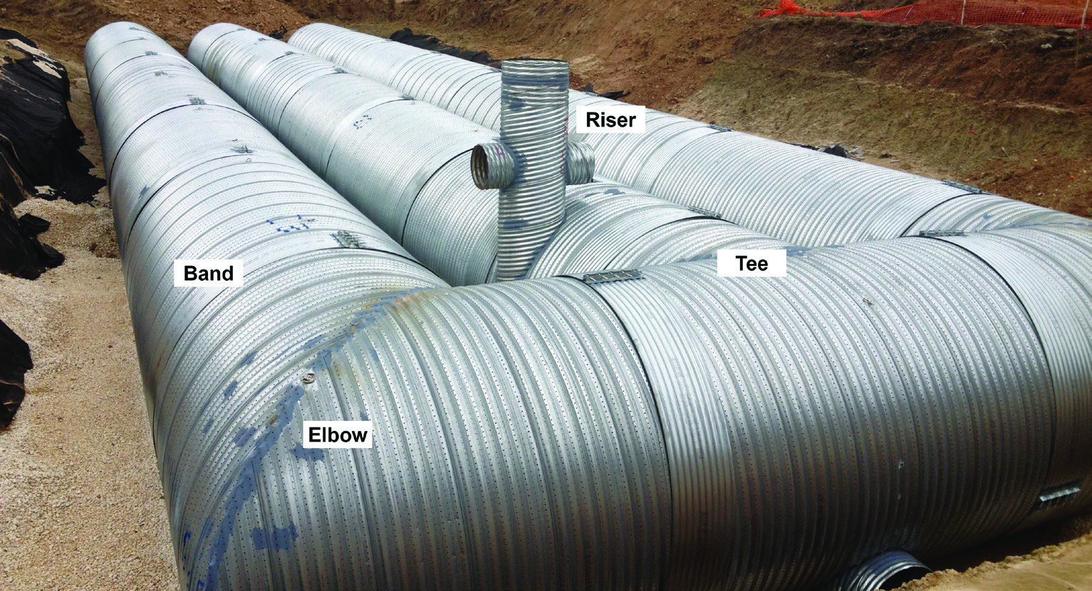
1. Overlapping welds—Risers can’t be located in the middle of an elbow, as this would result in overlapping welds, which weaken the structure. Risers generally are offset and are best placed on the barrel as opposed to the header. The accompanying picture illustrates the proper placement of a riser.
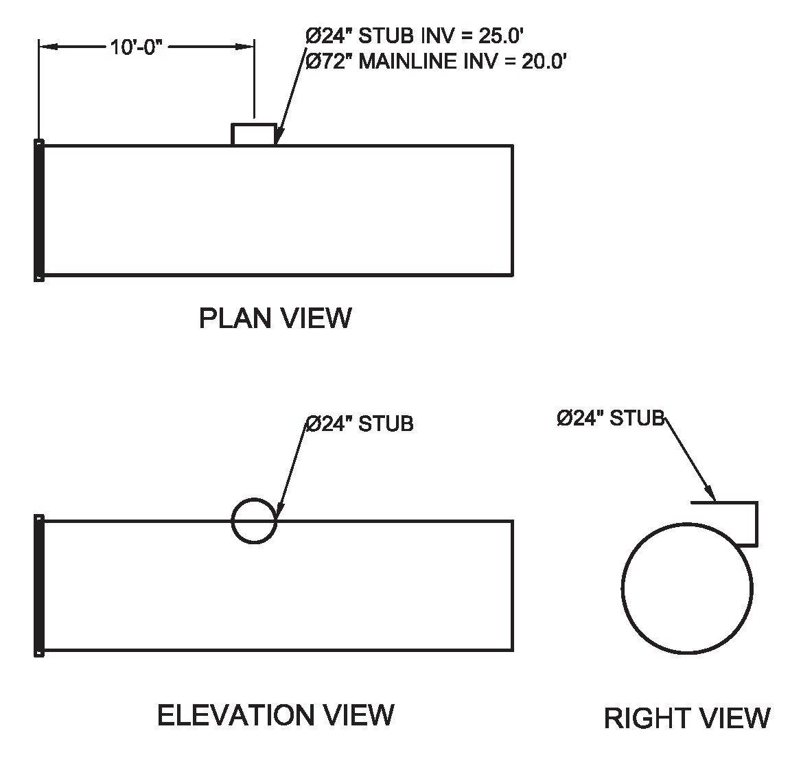
2.Stub elevations—Stub elevations may look acceptable in plan view, but you need to consider the profile views as well. This may seem obvious, but it’s easy to overlook when looking at a busy set of plans.
Sample Stub Elevations
3. Pipe spacing—Proper pipe spacing and backfill are crucial in performance CMP detention systems. Spacing is important, as there needs to be room for the contractor installing the system to get between the pipes and work the backfill material for proper compaction. The industry standard for spacing is as follows:
• Less than 24-inch diameter: use 12-inch spacing
• 24-inch to 72-inch diameter: use half the diameter of the pipe for spacing
Proper Riser Placement
• Greater than 72-inch diameter: use 36-inch spacing
4. Pipe installed under slopes—You should avoid installing systems under a steep cross slope or next to a slope. For example, it would violate industry guidelines to install a system with 20 feet of cover over one side, and 2 feet of cover over the other. This may result in a potential for failure due to a large difference in loads from one side to the other. Wet soils exacerbate these effects, so this is especially true for any detention material that relies on stone storage, not just CMP.
5. Systems designs at or near a building/structure— CMP detention systems can’t support loading from buildings and other structures. Risks and designs must be analyzed on a project-specific basis.
6. Minimum cover for heavy off-road construction equipment—Operating heavy construction equipment over or adjacent to flexible pipe installations will likely require additional protection for the pipe structure compared to that provided by the required minimum cover heights for normal highway traffic.
7. High groundwater and buoyancy—Whenever the watertable level is above the invert of the pipe, the potential for flotation exists and should be accounted for in the design.
8. Maintain minimum cover requirements—This will ensure the integrity on the system. The values below represent the minimum cover requirements. Cover is measured from the crown of the pipe to the bottom of flexible pavement or the top of rigid pavement.
• 12 inches to bottom of flexible pavement for CMP diameters 96 inches and smaller
• 18 inches to the bottom of flexible pavement for CMP diameters ranging from 102-144 inches
Authors
Patrick Valentine, EIT,is a Stormwater Design Engineer for Contech Engineered Solutions. He graduated from Virginia Tech with a Bachelor of Science degree in Civil & Environmental Engineering. As a Stormwater Design Engineer, his role at Contech requires him to design stormwater solutions that address challenges, including treatment for water quality, underground detention storage, subsurface infiltration and rainwater harvesting. Patrick can be reached at[email protected].
Quiz Instructions
Online quiz for this article is not active and PDH credit is no longer available.
This article is being maintained for informational purposes only.
Learning Objectives
Understand the value of an underground detention system.
Explain how a detention system can be designed and configured to provide the most economical solution.
Identify design elements commonly overlooked when designing CMP detention systems.