CSP for Vertical Applications | Understanding Design, Applications, and Practices
By Darrell Sanders, P.E., Noah Schenck, & Marcela Arbaiza
Introduction
Corrugated steel pipe (CSP) and structural plate products have been produced since the early 1900s and have since been expanded to a variety of applications. CSP and structural plate products are designed with a profile wall to provide a more efficient strength-to-material ratio. This strength, paired with its durability and dependability, has allowed it to be a versatile product since its inception.
A prevalent use for these products is vertical applications, which includes caissons for utility poles in electric transmission lines, bridge and building piers, wind-tower foundations, crane enclosures, utility sewer shafts, petroleum cellars (pits), general concrete forms, and more. These applications often are temporary structures used as forms or construction aids but not intended for long-term structural support. They can be constructed using CSP, structural plate or tunnel liner plate.
These vertical shafts can be galvanized, aluminized, polymer-coated or remain as black steel, depending on the needs of each specific project. Galvanizing is the most widely used and economical. This metallic coating is utilized for its added protection and extension to service life. In addition to forming a physical barrier against corrosion, the zinc coating sacrifices itself slowly by galvanic action to protect the base steel; this process will continue so long as zinc remains. Aluminized Steel Type 2 (ALT2) is a coating option that provides protection against a wider environmental range, allowing for a longer, maintenance-free service life. This coating is produced by hot-dipping steel in commercially pure aluminum. Heavy-gage polymer coatings offer longest-term protection for steel products by providing increased abrasion and corrosion resistance. This tough layer, bonded to both the inside and outside of Contech’s galvanized CSP, serves as a protective barrier, resisting corrosion from acids, salts and alkalis. Black steel offers high strength but is only used in temporary applications with gentler environments because of its lack of environmental resistance.
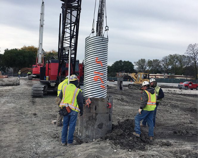
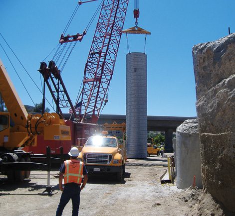
Figure 1. CSP being placed vertically to provide a form for the deep foundation.
CSP Primer
CSP was first utilized as construction caissons in Chicago; the sites near the lake had exceptionally poor soil conditions that created a need for deep foundations. Typically, deep foundations would be created using a wooden pile technique, but this process can damage nearby buildings during the driving process. The need for a new foundation process led to the utilization of CSP placed vertically as a construction aid for a cast-in-place concrete foundation to be created. This new technique also allowed taller buildings to be designed, introducing more skyscrapers.
Caissons are put in place for building foundations, transmission lines, bridge piers and wind-turbine foundations. Not only do the foundation requirements for the structure dictate the safety measures, but also the site conditions. For example, pier-rock installations require a minimum safety factor of four, while turbine foundations only require a factor of two. Standard deep foundations typically are manufactured utilizing HEL-COR CSP.
When site conditions—such as the presence of hard rock—dictate a more-complex design, an anchor foundation design is utilized. This design consists of a large-diameter, cast-in-place annular pier, typically 14 to 16 feet in diameter and 25 to 35 feet deep. These systems are ideal for mountainous areas and remote access sites or when seismic activity, floodwater inundation, flood scour, frost depth, creeps or landslides are a concern. Anchor foundations excel in every soil type and provide the lowest site disturbance during construction. Steel structural plates are predominantly used for anchor foundations due to the large diameters required for applications such as wind turbines. The outer rings can range from 30 to 36 feet, while the inner rings range from 10 to 14 feet. Caissons still are widely used today as an aid to ensure solid foundations for structures are installed without creating damaging conditions for the surroundings.
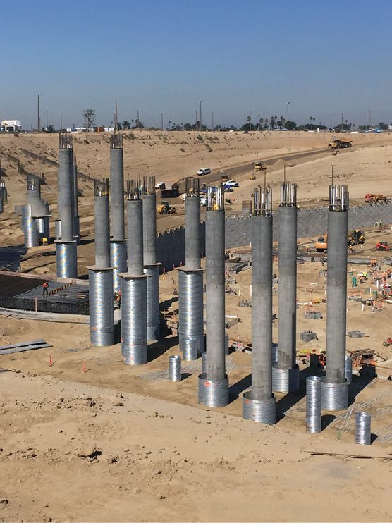
Figure 2. Large-diameter caissons being used as a foundation in a high-seismic-activity site.
Installing Vertical Shafts
CSP, structural plates and steel liner plate products all can be utilized to line vertical shafts. Vertical shafts can be constructed either through tunneling or sinking; the shaft must be constructed from the top down, as there’s initially no access to the bottom. In stable ground conditions, where a bored hole can stand for a short period without support, shaft linings often are picked up and inserted into the hole in a single piece. This installation procedure is used for CSP and structural plate.
Where ground conditions demand, shafts can be excavated from the surface in stages with segmented Tunnel Liner Plate being constructed in the hole as it’s excavated. The loads on vertical structures are substantially different than those on traditional buried pipes. Structural considerations change for non-standard applications when the pipe is not backfilled or when it is placed on end.
Vertical shafts can vary in diameter from a few feet to 50-plus feet and frequently have depths exceeding 60 feet. Not only do these structures’ vertical orientation change the pressures exerted on them, but the depths they can extend factor heavily into the design. Unlike buried structures, soil loads on vertical pipes are limited to only the active soil pressure acting on the shaft, which can be as small as a third of the soil prism load a buried pipe would experience. Loads exerted by lateral earth pressures should be calculated throughout the entirety of the shaft, since lateral earth pressure varies linearly with depth.
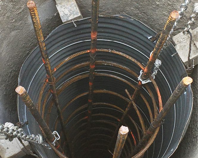
Figure 3. Different installation methods for vertical applications.
Localized soil instabilities and sloughing can result in differential pressures that the pipe experiences. This lateral earth pressure acts parallel to the slope of the backfill; the resultant earth pressure acts at a distance approximately one-third of the pipe height from the base. Active soil pressure develops when the soil mass settles to fill the gap between the bored hole and the installed structure. Conversely, if the structure wall expands into the soil, the soil mass is compressed and passive soil pressure develops. This situation may occur along the section of wall that’s below grade and on the opposite side of the retained section of fill.
After a shaft penetrates the water table, the hydrostatic load of the water is added as a surcharge to the active pressure of the buoyant soil around it. Shafts typically are designed to prevent hydrostatic pressure from developing, but in cases where water pressure may develop behind an undrained shaft, the pipe also must be designed to resist buckling under uniform external pressure.
Hydrostatic pressure is one of many causes of surcharge loads. These can include a line load, strip load, embankment load, floor loads and temporary loads such as construction traffic and stockpiles of material. As is the case with horizontal buried structures, careful consideration of all conditions within a site must be accounted for to ensure successful implementation of the structure.
The minimum stiffness required to endure these loads is expressed by the formula,
where D is the neutral axis diameter or span (in), E is the modulus of elasticity (psi), and I is the moment of inertia (in4/in). In vertical applications, the design thrust in the plate should be computed in the same manner as for tunneling applications. In tunneling applications, a minimum factor of safety of three for seam strength is common and is required per the AASHTO specifications. Final determination on this factor of safety should be based on detailed knowledge of the project, soil conditions and practical experience.
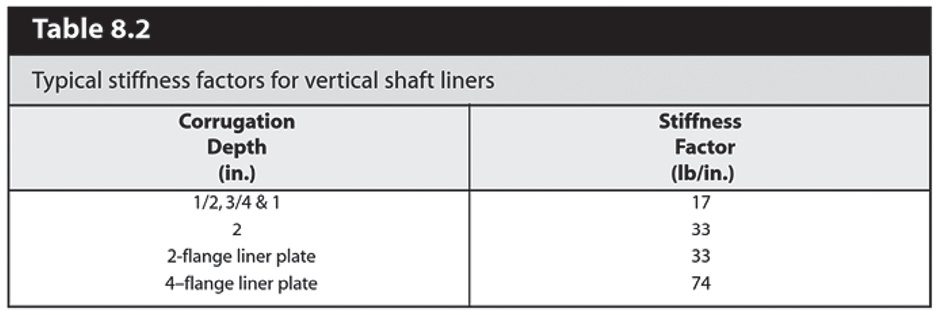
There is a suggested factor safety of two, but the requirements for temporary structures can change depending on the level of knowledge on the ground conditions (and resulting loads), the degree of safety to protect the bore and if workers will be inside the shaft as it is excavated. For these reasons, vertical shafts are designed more conservatively than most other applications. The contractor or engineer should provide stiffness limits, but when they are not provided, suggested stiffness factors for vertical shafts are given within the NCSPA manual as shown below.
Maintaining shaft integrity is critical when dealing with vertical applications, especially when workers are operating within the shaft. The effectiveness of the structure depends on multiple factors such as specific site conditions, construction practices, material, installation and supplementary factors that must be analyzed.
The structural design requirements and procedures for corrugated flexible metal pipe structures such as CSP, structural plate or tunnel liner plate is covered in the AASHTO specifications. However, since those design standards were developed for structures installed horizontally, special consideration must be given for vertical shaft construction and installation practices. Vertical applications are designed using the lateral earth pressure design, which acts parallel to slope of the backfill. This pressure depends on the soil type, water-table height and additional construction loads that may be present around the shaft. In addition to the stiffness of the vertical shaft, selecting the correct material and coating play an important role in determining the structures’ reliability and longevity.
The project engineer is responsible for determining the loads exerted on the shaft, performing structural checks for seam strength and critical buckling, and determining the shafts’ stiffness, which can require reinforcing the design as necessary. The development of utilizing vertically placed corrugated structures has helped expand the relevance of a product that was developed more than a hundred years ago.
Examples of Versatility
Examining the following case studies of HEL-COR CSP vertical applications helps illustrate the versatility and effectiveness of these site solutions.
During construction of the Robert Crown Community Center in Evanston, Ill., the challenge of overcoming poor soil conditions needed to be solved. The site was near Lake Michigan, resulting in unstable soil composed of glacial till, thin deposits of silt, clay and sand. Erecting a structure using shallow foundations in these conditions would lead to an unacceptable degree of building settlement. As a countermeasure, a deep foundation system of caissons that extend roughly 50 feet below grade were designed. Installation of the caissons would be impossible without temporary casings created using HEL-COR CSP because of the non-cohesive nature of the in-situ soils. Approximately 146 caissons were constructed with this method, allowing for an acceptable foundation to be put in place.
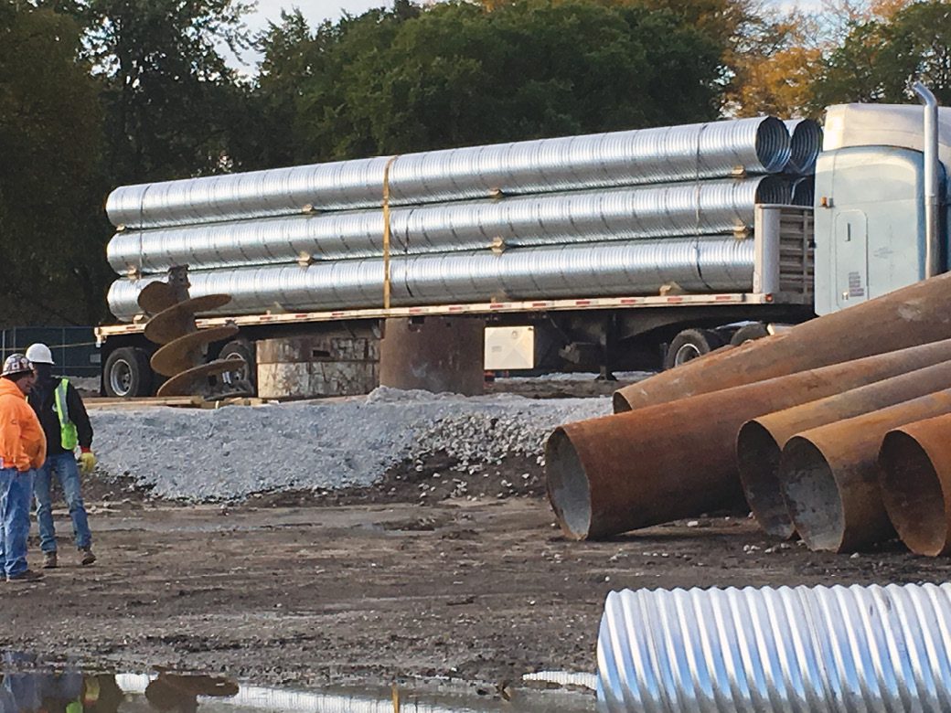
Figure 5. HEL-COR loaded on a truck for caisson use in Illinois.
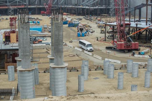
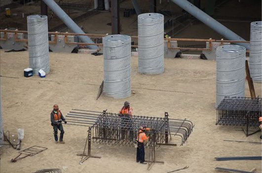
The construction of SoFi Stadium in Inglewood, Calif., had a unique challenge to overcome before construction could begin. The site location is known for its frequent and extreme seismic activity, which could lead to catastrophic consequences at this pedestrian-heavy destination. To negate the effect of soil movement on the structure, a “seismic moat” system was designed. This design has a similar concept to bridges on rollers, allowing for the surroundings to move independently from the structure, preventing failure in the case of seismic events.
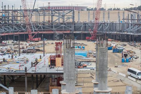
Figure 6. Support columns with CSP isolation casings.
To translate this into foundation design, HEL-COR CSP “isolation casings” were installed around the structural concrete support columns. This created a casing/airgap between the columns and its surrounding soil, which not only eliminates the active pressure from soil surrounding the foundations, but also allowed for shifting ground conditions to have no effect on the structure. Special coupling band designs were utilized to allow these heavy-gage metal casings to be stacked vertically, reaching heights of up to 100 feet. This monumental project incorporated approximately 25,000 linear feet of HEL-COR CSP when completed and is the newest beacon in the National Football League, all thanks to vertical site solutions of metal pipe.
Figure 7. Photos demonstrate the size range of CSP utilized at SoFi Stadium. Workers are shown alongside the smaller caissons for scale.
As demonstrated by these case studies, the use of vertical CSP in construction can allow for structures to exist in adverse conditions with relative ease. The market for this product has expanded since its conception and will continue to expand due to its reliable strength, durability and versatility. It has become a go-to site solution for more than 100 years now and exists worldwide, whether visible from the surface or buried.
Click on the button below to start the quiz for this course. Your score will be tabulated while you wait, and you will receive your certificate upon completion if you correctly answer eight or more questions.
Registration on v1-education.com is required to access the quiz. Use the "Sign Up" link in the top right of v1-education.com to register. If you are already registered simply enter your credentials to access the quiz.
The Professional Development Series is a unique opportunity to earn continuing education credit by reading specially focused, sponsored articles in Informed Infrastructure.
If you read the following article, display your understanding of the stated learning objectives, and follow the simple instructions, you can fulfill a portion of your continuing education requirements at no cost to you. This article also is available online at v1-education.com.
Learning Outcomes
At the conclusion of this article, the reader should be able to understand/perform the following:
Identify the applications and benefits of using corrugated steel pipe for vertical applications.
Identify the different material and coating options to meet site-specific needs.
Understand how site and ground conditions affect the vertical shafts’ construction and installation practices.
Understand the concept of pipe stiffness factors and how the limits affect the design of the vertical shaft.
Identify the use of ring beams and when/why they are necessary.
Understand how the pressure applied to the shaft depends on the soil type, water-table height and other loads that may be applied to the shaft; and how these lateral pressures will be used in the design process for the vertical shaft liner.
Quiz Instructions
Click on the button below to start the quiz for this course. Your score will be tabulated while you wait, and you will receive your certificate upon completion if you correctly answer eight or more questions.
Registration on v1-education.com is required to access the quiz. Use the "Sign Up" link in the top right of v1-education.com to register. If you are already registered simply enter your credentials to access the quiz.