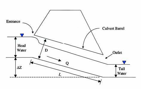
A culvert is a relatively short segment of conduit that is typically used to transport water underneath a roadway or other type of earthen embankment. There is some common terminology that is used in culvert hydraulics that can best be presented by referring to Figure 1. The culvert itself consists of an entrance, an outlet, and a culvert barrel. Common culvert shapes include circular pipes, rectangular boxes, ellipses, and arches. Noncircular culverts are generally described by their size in terms of a culvert rise (D) and a culvert span (B). The size of a circular culvert is usually expressed in terms of the culvert diameter (D).
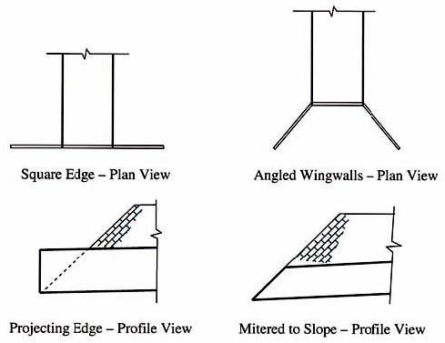
There is a wide variety of entrance conditions found at culverts, including square edge, angled wingwalls, beveled edges, entrance mitered to slope, et cetera. Some of these common culvert end treatments are shown in Figure 2. It is not uncommon for the opening of a culvert to be smaller than the original channel cross-section prior to the culvert installation. All else being equal, a smaller waterway opening will result in a lower channel conveyance, that is, a lower carrying capacity of the channel. For the same flow, a lower conveyance will, in turn, result in a higher depth of water upstream of the structure, called the headwater.
In today's environment of floodplain management and regulations, the increase in water surface upstream of culverts is often limited. Therefore, culvert designs that convey water under roadways with minimal headwater buildup are becoming more common. The hydraulic solution to minimize the head loss would be to not constrict the flow by spanning the entire conveyance channel. However, economic considerations many times prohibit this approach. While some increase in water level upstream of the culvert may be tolerated, the basic principle behind culvert design is to ensure that the water level increase is not unacceptably high. The headwater can be estimated using well-established design methodologies.
Many installations use three-sided culverts, where the bottom of the culvert is typically the natural channel bottom.
Historically, most culverts were closed conduits, where the same material is found on the top, bottom, and sides of the culvert, for example, a corrugated metal pipe culvert. With environmental regulations becoming more stringent, many culvert installations utilize three-sided culverts. A three-sided culvert is a structure that has the same material on the top and sides of the structure. The bottom of the culvert is typically the natural channel bottom. The most commonly used culvert materials are concrete, corrugated metal, and plastic. Usually, the internal roughness of a culvert is a function of the culvert material. However, for a three-sided culvert, where the bottom of the installation is the natural channel, the internal roughness is a function of the culvert material and the roughness of the channel itself.
Figure 1: Culvert geometry
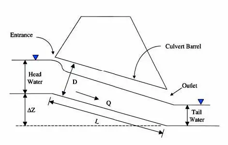
Culverts are usually laid on a slope, which can be found by dividing the elevation difference between the upstream and downstream ends of the culvert (?Z) by the culvert length (L ). Typically, the slope is downward such that the outlet elevation is lower than the inlet elevation. In some cases, culverts may be laid horizontal or on an adverse slope where the downstream elevation is higher than the upstream elevation.
The tailwater at a culvert is the depth of water at the downstream end of the culvert, as measured from the downstream invert of the culvert. The tailwater must be known or estimated prior to performing the culvert hydraulic calculations. There are various methods to estimate the tailwater at a culvert. One method is to estimate a downstream channel shape and use Manning's equation to calculate a tailwater depth. Another method is to conduct a water surface profile analysis of the steam reach downstream of the culvert.
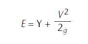
For a given design discharge (Q), there will be a corresponding headwater depth (HW) upstream of the culvert entrance. In fact, it is the headwater depth that pushes or forces the design discharge through the culvert opening. For a given culvert opening, a higher discharge will typically result in a higher headwater depth since more energy is needed to force the flow through the culvert. In open-channel hydraulics, energy is synonymous with water depth as shown in Equation 1.
Equation 1:
Where:
E is specific energy (feet);
Y is depth of water (feet);
V is mean water velocity (feet per second);
g is acceleration due to gravity (feet per second per second).
Culverts are frequently designed to pass some specified design discharge without creating an unacceptably high headwater depth. Thus, for an engineer to design a culvert successfully, the headwater depth for the design discharge must be reliably predicted. For many applications, the culvert design discharge is frequently associated with the 1-percent, 2-percent, or 4-percent annual chance storm event. Knowledge of the headwater depth associated with a particular flow condition will reveal to the engineer whether or not the culvert will pass the design flow safely — without overtopping the embankment or violating applicable regulations. The definition of an unacceptable headwater depth may vary among sites, but typically, the maximum headwater elevation should be about 1 or 2 feet lower than the roadway shoulder elevation to minimize the potential for roadway flooding. Of course, other factors, including site conditions and construction schedules, contribute to the final culvert design specifications. Nonetheless, it is important for engineers and others involved with culverts to be able to predict the hydraulic performance of these structures accurately so that they operate without any undesirable effects.
Figure 2: Common culvert end treatments
Standard FHWA culvert design approach
According to research sponsored by the Federal Highway Administration (FHWA), culvert operation is governed at all times by one of two conditions: inlet control or outlet control (Normann, et al, 1985). Inlet control is a common governing situation for culvert design, characterized by the fact that the tailwater or culvert barrel conditions allow more flow to be passed through the culvert than the inlet can accept. The inlet itself acts as a controlling or governing section of the culvert, restricting the passage of water into the main barrel.
Outlet control is different from inlet control in that the barrel or tailwater cannot accept as high a flow as the inlet may allow. This may occur with a high tailwater or a long culvert with a rough interior. Outlet control may be mathematically modeled using water surface profile methods or by an energy balance. Because outlet control conditions in culverts can be calculated with open-channel hydraulic principles, there is no need for empirical testing and regression formulas to describe the relationship between the flow through the culvert and the headwater. However, testing on scale models can provide valuable information about the head loss coefficients associated with the culvert entrance. Once the outlet control situation has been modeled as accurately as possible based on known information, the headwater may be calculated to evaluate the culvert design.
The FHWA has standardized the manner by which culverts are examined and designed. The design approach involves first computing the headwater elevation upstream of the culvert assuming that inlet control governs. The headwater elevation is then also found assuming that outlet control governs. The two headwater values are compared with one another and the higher of the two is selected as the basis of the culvert design.
Generally speaking, the procedure described above is repeated for different types of culvert shapes, sizes, and entrance conditions. The least expensive culvert that produces an acceptable headwater elevation is typically chosen for the final design. Of course, site conditions, structural considerations, permit requirements, or aesthetic appeal may also influence the choice of culvert design.
Inlet control
Inlet control represents a much more complex hydraulic environment than outlet control, and it cannot be strictly mathematically modeled to obtain headwater depths. Under inlet control, the flow patterns at the entrance to the culvert may be three dimensional with vortices or other unpredictable features. These patterns are influenced by a number of factors, the most important of which are inlet geometry, wingwall configuration, culvert shape, and degree of beveling. Fortunately, culverts operating under inlet control can be modeled using regression equations.
For many years, inlet control culverts modeled using the methodology outlined in the FHWA Hydraulic Design Series No. 5 (HDS-5) – Hydraulic Design of Highway Culverts have successfully withstood both extensive laboratory tests as well as the test of time in field installations. Empirical measurements on small-scale models of varying inlet geometries and wingwall configurations led to derivation of unique regression coefficients for each case. These models possess remarkably similar hydraulic characteristics to their full-size counterparts and provide the best approximation of how a particular culvert shape will perform in the field (Normann, et al, 1985).
Because inlet control represents the case where the culvert barrel will convey more flow than the inlet will accept, the culvert normally will not flow full for its full length, thereby resulting in a free water surface that exists along the length of the structure. Under inlet control, the culvert entrance may either be unsubmerged or submerged. Figure 3 shows the latter case.
Figure 3: Example of submerged inlet control
At low flows, the culvert entrance is unsubmerged and the discharge through the culvert entrance behaves like weir flow. A weir is a flow control cross-section where the discharge and depth of water are related to one another through some predictable relationship. At much higher flows, the culvert entrance is submerged and the flow through the entrance acts like orifice flow. Orifice flow represents the case where an opening is submerged and the discharge through the opening increases as the depth or head above the opening increases.
One example of where inlet control occurs is when there is a mild channel slope upstream of the culvert that transitions to a steep culvert slope (Norman, et al, 1985). The transition from a mild slope to a steep slope causes a change in the flow regime from subcritical to supercritical flow. The change from subcritical to supercritical flow results in critical depth occurring at or near the entrance to the culvert. In some cases, such as short, smooth culverts, the nature of the culvert entrance can cause inlet control to occur even if the culvert slope is mild or flat.
While the behavior of flow at the entrance to a culvert is extremely complex, the primary influencing factors for headwater depths are the type of opening (pipe, box, arch, et cetera), the size or area of the culvert opening, and the entrance conditions. Commonly found entrance conditions include square edge with headwall, end mitered to the slope, projecting barrel, and beveled entrance. Culvert inlets may also utilize wingwalls placed at an angle from the culvert barrel. Not only do wingwalls provide structural stability to the culvert and act as retaining walls for fill slopes, they can also perform a hydraulic function by funneling flow into the culvert opening.
Recall that the complexity of the hydraulics associated with inlet control, when combined with the large number of different shapes, sizes, and entrance conditions available for culverts, make it nearly impossible to develop a single formula capable of describing the hydraulic behavior of culverts operating under inlet control. As a result, empirical methods are typically used to evaluate inlet control.
Inlet control equations are presented in HDS-5 that describe unsubmerged and submerged inlet control (Normann, et al, 1985). For the unsubmerged case, two expressions can be used as shown in Equations 2 and 3. While both expressions provide acceptable results, Equation 2 is theoretically more accurate, while Equation 3 is easier to apply. Additionally, the latter equation is easier to use when developing regression coefficients from observed headwater depths and discharges or when the critical depth through a structure is not easily determined.
Equation 2:
Equation 3:
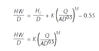
Where:
HW is headwater depth at the culvert entrance (feet);
HC is specific energy at critical depth (feet);
Q is discharge through the culvert (cubic feet/ second (ft3/s));
A is full open area of the culvert (square feet);
D is culvert rise (feet);
S is the slope of the culvert barrel (feet/foot);
K and M are inlet control regression coefficients for unsubmerged conditions.
Either form of the two equations above will produce acceptable results (Normann, et al,1985). For model studies, quantities measured in the lab are typically the headwater (HW) and the discharge (Q). Other known quantities include the area of the model (A), the model rise (D) and the slope of the channel. When developing regression coefficients using Equation 2, the specific energy at critical depth must be computed and used in the regression analysis. Use of Equation 3 avoids the need to make these additional calculations.
When the culvert entrance is submerged, a different equation must be applied to find the headwater depth under inlet control (see Equation 4). As with the case of unsubmerged inlet control, model studies are typically used to develop the inlet control regression coefficients.
Equation 4:
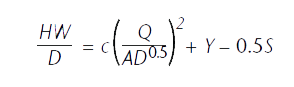
Where:
HW, Q, A, D, and S are as previously defined;
c and Y are inlet control regression coefficients for submerged conditions.
Outlet control — culvert flowing full
In HDS-5 design methodology, outlet control is determined assuming that the culvert is flowing full. The headwater due to outlet control is found from Equation 5, which is an energy balance between the upstream and downstream ends of the culvert.
Equation 5:

Where:
HW is headwater depth above the inlet invert (feet);
EL0 is the elevation of the culvert invert at the outlet;
H0 is the governing tailwater (feet);
hL is head loss through the culvert (feet).
To find the governing tailwater, H0, the critical depth in the culvert must first be determined. The critical depth is then used with the culvert size and compared to the specified tailwater as shown in Equation 6.
Equation 6:
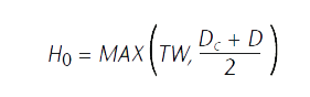
Where:
TW is the tailwater at the downstream end of the culvert (feet);
DC is critical depth in the culvert (feet);
D is culvert diameter or rise (feet).
The head loss through the culvert, hL , is found by considering all losses, including entrance losses, exit losses, and friction losses. Manning's equation is rearranged to quantify friction losses. Equation 7 can be used to determine the head loss through a culvert. If bends occur along the length of the culvert, then these losses must also be included in Equation 7.
Equation 7:
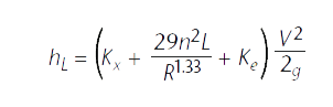
Where:
Kx is an exit loss coefficient;
n is Manning's roughness coefficient;
L is the length of the culvert (feet);
R is the hydraulic radius of the culvert (feet);
Ke is an entrance loss coefficient;
V is velocity in the culvert (feet per second);
g is the gravitational constant (feet per second per second).
Values for the entrance loss coefficient, Ke, are available in various hydraulic texts including HDS-5, and values range from 0.20 to 0.80, depending on the inlet type and configuration. Values for exit loss coefficients, Kx, can vary between 0.3 and 1.0. For a sudden expansion of flow, the exit loss coefficient is set to 1.0. The exit loss coefficient should be reduced as the transition becomes less abrupt (HEC-RAS Hydraulic Reference Manual, 2002).
For culvert applications where a natural bottom is used, a composite Manning's roughness coefficient must be computed. There are several assumptions that can be used to determine a composite roughness value. One common assumption is that each part of the area has the same average velocity, which is equal to the average velocity of the whole section (Chow, 1959). With this assumption, the composite Manning's roughness, nc , may be obtained by Equation 8:
Equation 8:
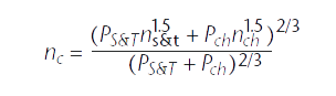
where:
Ps&t is the wetted perimeter of culvert sides and top(feet);
Pch is the wetted perimeter of the natural channel(feet);
ns&t is Manning's roughness for the culvert sides and top culvert; and
nch is Manning's roughness for the natural channel.
Outlet control — culvert flowing partially full
The methodology in HDS-5 using the equations from the procedure outlined above assumes that the culvert is flowing full along the entire length. A common design case occurs when it is necessary to minimize the head loss through a culvert. The minimal headwater rise, small slope, and high relative tailwaters associated with these conditions usually result in outlet control. In this outlet control case, the culvert is most likely to be flowing partially full. In this case, a water surface profile analysis is necessary to determine the losses through the culvert accurately. The profile analysis is conducted from the downstream end to the upstream end of the culvert.
For culverts flowing partially full, the most efficient method to compute the water surface profile in the culvert is the direct step method. The direct step method computes the water surface profile at increments of known depths. The first step is to compute the exit loss and establish a starting water surface inside the culvert at the downstream end. The starting water surface will either be critical depth or the result of an energy balance between the tailwater and a cross section just inside the culvert on the downstream end. Once a water surface is computed inside the culvert at the downstream end, the designer performs the direct step calculations along the length of the culvert. After the depth of water is determined at the upstream end, the entrance loss is added in to compute the headwater depth.
Summary
A successful culvert design depends on accurately predicting the effect that a culvert will have on the surrounding area. Typically, culverts can be expected to cause changes in the water surface elevation upstream. The designer must estimate these effects to ensure that the change to water elevation upstream headwater will not adversely affect the surrounding community. The techniques to design culverts hydraulically were developed more than four decades ago. More stringent floodplain and environmental regulations are changing the types of culverts design engineers are specifying today. However, these traditional culvert hydraulic design procedures are still applicable when used with modifications to reflect the current culvert crossing characteristics.
Philip A. Creamer, P.E., is director of Bridge Design Services with CONTECH Bridge Solutions Inc.

