The majority of plastic pipe currently installed in the United States is manufactured using a solid wall profile. The technology used to produce solid wall pipes is relatively simple and the manufacturing equipment required to produce a solid wall pipe product is available from a wide variety of producers. Little research and development cost is required to enter into the market with a solid wall product. Generally, existing product and design specifications are already in place that can be used to minimize marketing and selling expenses for the product. Finally, the number of vendors available to provide ancillary products such as fittings and manhole connections is much greater when working with a solid wall pipe versus a profile wall product.
Therefore, why would a producer want to spend extra time and expense to develop and market a profile wall product? The answer is because a well-designed profile wall pipe can utilize material more efficiently, thereby decreasing material costs and potentially providing the product with a competitive advantage in the marketplace. Profile wall pipes are defined as "a pipe wall construction that presents a smooth interior wall in the waterway but includes ribs, corrugations, or other shapes, which can be either solid or hollow, that helps brace the pipe against diametrical deformation" (ASTM F2306/F2306M). By incorporating ribs, corrugations, or other shapes, the desired pipe wall, moment of inertia, and moment capacity of the wall section can be achieved with less material than for a comparable solid wall pipe profile.
For gravity flow pipes, often the fundamental performance requirement that plastic pipes have to meet for acceptance in the marketplace is pipe stiffness. Pipe stiffness is generally measured using a methodology described in ASTM D2412, Standard Test Method for Determination of External Loading Characteristics of Plastic Pipe by Parallel- Plate Loading. This test method requires a pipe sample to be conditioned to a room temperature of 73°F and placed between parallel plates controlled by a hydraulic load cell. The pipe is then deflected at a standardized rate of 0.5 inch per minute. The load required to deflect the pipe by a given amount, generally 5 percent of the diameter, is recorded. Pipe stiffness (PS) is calculated using Equation 1:
Equation 1:
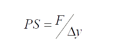
Where:
F is load per unit length required to deflect the pipe to the deflection level in pounds per inch (lb/in.);
?y is pipe deflection in inches.
For small deflections, the performance of a given pipe wall in a pipe stiffness test correlates closely to its relative wall stiffness, EI. The wall stiffness is the product of the stiffness of the material measured by its flexural modulus (E) and the stiffness of the geometric wall profile (I). For thermoplastics, the modulus of a given material varies on its temperature and the rate at which the material is strained. Even within a common classification of thermoplastics such as high density polyethylenes (HDPE), the flexural modulus can vary significantly based on the density of the material.
Figure 1: Typical cross section elements of a profile wall pipe.
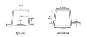
The moment of inertia for an element is strictly a function of geometry. For a solid wall pipe, the moment of inertia is equal to the cube of the wall thickness (t) divided by 12 (t3/12). For profile wall pipes, the contribution of each wall element must be determined separately and then properly combined to arrive at the theoretical moment of inertia for the pipe wall cross section. A typical cross section can be broken into its individual elements as shown in Figure 1.
The contributions of each individual element are summed together to compute the moment of inertia for the cross section using Equation 2:
Equation 2:
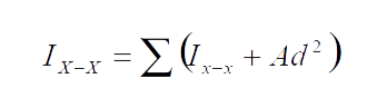
In this formula, the overall moment of inertia (I) is calculated by summing the moment of inertia of each element about its own centroid plus the product of the element's cross sectional area (A) and the square of the distance from the element's own centroid to the centroid of full cross section (d). The key here is that the area of each individual element contributes to the overall moment of inertia by the square of the distance from it's own centroid to the centroid of section. By creating a tall wall profile that has elements far away from the centroid of the cross section, a very high moment of inertia can be developed with far less wall area when compared to a solid wall profile section.
Since pipe stiffness correlates closely to the EI stiffness of a wall profile, assuming pipe sections are made from the same material, a profile wall that achieves the same moment of inertia as a solid wall pipe with less wall area will provide a more efficient cross section and lower material costs for the producer.
Other considerations for profile wall pipe design
While designing a pipe wall section that will provide the required section properties to compete in a particular market is important, other considerations must be accounted for to properly qualify the adequacy of the design. One of the principle checks that needs to be performed is a stability check for the profile at the performance limits for the product.
In the past, some pipe sections have been designed and tested only to discover that, when the pipe deflected or heavy service loads were applied to the pipe, portions of the pipe wall would buckle and the pipe wouldn't perform at the level the section properties implied that it should. This is because some of the members were not fully effective at strain levels that could occur within the service limits for the product. The result was elements that buckled or deformed in service. This can be a particular problem for elements that include the waterway wall, which needs to be smooth to maintain the pipe's hydraulic capacity.
Recognizing that local stability problems were a potential problem for profile wall pipes, the current AASHTO Load and Resistance Factor Design (LRFD) Bridge Design Specifications for thermoplastic pipes, Section 12, includes a methodology that allows a wall profile to be evaluated to determine if the wall elements are fully effective. If they are not, the specification provides a methodology for determining what portion of the element can be considered effective in the computation of the profile's section properties. This effective width concept is shown in Figure 2.
Figure 2: A portion of the element's width may be determined
to be ineffective, and therefore ignored in calculating section properties..
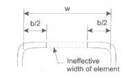
For hoop compressive loadings, any portion of the element that is considered to be ineffective at the strain levels for the anticipated performance limits for the pipe is ignored and the effective section properties are computed as if the material considered ineffective does not exist. AASHTO also considers that strains caused by overburden loads are not the only strains that need to be considered. Because thermoplastic pipes are flexible, bending strains due to pipe deflections are also considered. The LRFD code provides methodologies to check both the total compressive and tensile strains within the pipe wall. The primary concerns about excessive compressive or tensile strains are for different reasons. Excessive compressive strains are primarily a concern because they can lead to buckling of the pipe wall members. Tensile strains are a concern because they can lead to premature cracking in the pipe wall.
Bending strains can be estimated using the AASHTO design methodology using Equation 3:
Equation 3:
Equation 4:
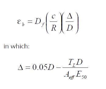
Where:
eb = bending strain (inch/inch)
Df = shape factor
R = radius to the centroid of the pipe wall profile(inches)
c = distance from the neutral axis to extreme fiber(inches)
? = deflection of pipe, reduction of vertical diameter due to bending (inches)
D = diameter to centroid of pipe wall (inches)
TL = thrust in the pipe wall (kip/foot)
Aeff = effective area of the pipe wall (square inches/foot)
E50 = 50-year modulus of elasticity for the HDPE material(ksi)
A quick analysis of the calculation of the deflection of the pipe shows that AASHTO is suggesting that that pipe be checked for a 5-percent in-service deflection level. The in-service deflection includes the decrease in the pipe wall diameter due to the overburden load and the subsequent foreshortening of the pipe wall. Obviously, other deflection levels could be evaluated by a designer if desired.
In evaluating the formula for computing the bending strain (Equation 3), there are two primary factors that need to be considered. First is the ratio of the distance from the outer fiber of the pipe wall section to the neutral axis of the section to the radius of the pipe. This demonstrates one disadvantage of using tall profiles to gain pipe stiffness; a tall profile also leads to higher tensile strains when the pipe is deflected. Therefore, composite HDPE products that use steel ribs or other stiffening features generally have an advantage over profiles manufactured exclusively with HDPE material because the higher modulus of the stiffening features generally allows them to achieve the required stiffness for the pipe profile with a lower overall wall height. A lower wall profile height translates to lower bending strains at the same pipe deflection.
Table 1: Pipe shape factor (Source: AASHTO)
Pipe Stiffness
(F/?yksi)
= El/ 0.149 R3 |
Pipe Zone Embedment Material and Compaction Level |
| Gravel (1) |
Sand (2) |
| Dumped to Slight (3) |
Moderate to High (4) |
Dumped to Slight (3) |
Moderate to High (4) |
| 0.009 |
5.5 |
7.0 |
6.0 |
8.0 |
| 0.018 |
4.5 |
5.5 |
5.0 |
6.5 |
| 0.036 |
3.8 |
4.5 |
4.0 |
5.5 |
| 0.072 |
3.3 |
3.8 |
3.5 |
4.5 |
1. GW, GP, GW-GC, GW-GM,GP-GC and GP-GM per ASTM D 2487 (includes crushed rock)
2. SW, SP, SM, SC, GM and GC or mixtures per ASTM D 2487
3. <85% of maximum dry density per AASHTO T 99, <40%relative density (ASTM D 4253 and D4254)
4. =85% of maximum dry density per AASHTO T 99, =40%relative density (ASTM D 4253 and D4254)
The second factor that contributes directly to the bending strain within a pipe wall is what AASHTO defines as the pipe's shape factor. The shape factor for a given pipe is as shown in a table from the AASHTO specification (Table 1). The shape factor is an empirical value that is affected by the stiffness of the pipe being considered, as well as by the type and level of compaction of the structural fill directly around the pipe. Therefore, pipes with greater pipe stiffness will deflect less and therefore experience lower bending strains. This is most significant in considering the tensile strains because those can lead to premature cracking in the pipe wall. AASHTO currently has a 5-percent allowable limit on long-term strain.
HDPE resins
HDPE is frequently chosen as a pipe material because it has many physical properties that make it effective for common piping applications. It has exceptional abrasion and chemical resistance; good structural characteristics; and can be easily extruded, injection, or rotationally molded into pipe profiles and parts. HDPE pipes are commonly used in pressurized gas and water transmission systems, gravity flow drainage systems, and many industrial applications.
All polyethylene resins are made of molecules composed of long chains of carbon atoms with hydrogen atoms bonded to the sides of the chain. A typical chemical diagram is shown in Figure 3.
Figure 3: Typical molecular structure of a polyethylene resin
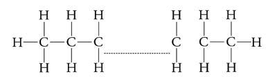
Some branching of short polymer chains off the sides of the long polymer chain can occur. The amount of side branching greatly affects the density of the resin. Variances in resin density can affect many physical properties. Some of these changes are listed in Table 2.
From a pipe-performance standpoint, higher-density resins provide higher tensile strength and stiffness properties. However, higher-density resins are also more strain sensitive and have less crack resistance. Therefore, pipe manufacturers need to balance the need for strength and crack resistance when selecting the resins for use in their pipe products. A higher-density resin allows a pipe manufacturer to obtain the required strength and stiffness for its pipe product with less material. However, the product is more prone to stress cracking over time, compared with a lower-density material. Composite pipes that use steel or other alternate materials to gain the structural strength required for the product can choose a slightly lower-density material that provides superior crack resistance under long-term loadings.
Table 2: Change in physical properties as resin density increases
| Property |
Increases |
| Tensile Strength (@ yield) |
Increases |
| Stiffness |
Decreases |
| Impact Strength |
Increases |
| Low Temp Brittleness |
Increases |
| Abrasion Resistance |
Increases |
| Hardness |
Increases |
| Softening Point |
Increases |
| Stress Crack Resistance |
Decreases |
| Permeability |
Decreases |
| Chemical Resistance |
Increases |
| Melt Strength |
--- |
| Gloss |
Increases |
| Haze |
Decreases |
| Shrinkage |
Increases |
To establish long-term design properties, some resins undergo controlled tests that subject resin materials to various constant stress levels and determine the time to rupture for each specimen. This data is used to develop the long-term physical properties for the material that can be used in the design of pipe products. Testing is performed in accordance with procedures described in ASTM D1598, Time to Failure of Plastic Pipe Under Constant Internal Pressure. This data is frequently submitted to a committee (the Hydrostatic Stress Board) to review and issue a hydrostatic design basis (HDB) for that material. These material properties are published, and the resin is designated as a pressure-rated resin. Because the testing process takes a long time and is quite expensive to perform, generally only the highest quality resins are tested to establish a pressure rating.
From a designer's perspective, specifying the use of products that use HDB-rated materials means that the resin being used in the manufacture of the pipe has a known set of long-term design properties. Certainly, many products use polyethylene resins that do not have a pressure rating, but the mechanical properties for those resins have to be extrapolated or inferred from other sources. Typically, higher performing pipe applications such as pressurized gas lines require the use of HDB materials in the manufacture of the pipe. While pressure-rated resins are generally more expensive, for long-term structural applications, many designers insist on the use of HDB-rated materials to provide a more predictable service life.
To compare and specify various polyethylene materials, many specifications use ASTM D3350, Standard Specification for Polyethylene Plastics Pipe and Fitting Materials. This specification categorizes polyethylene resins based on six primary physical properties of the material — density, melt index, flexural modulus, tensile strength, slow crack growth resistance, and hydrostatic strength classification. The specification assigns a number to each physical property of a given resin. The grouping of these numbers is known as a cell classification. Many specifications indicate the minimum performance limits required for resins used in the manufacture of the pipe by requiring a minimum cell classification for the material.
Properly designed HDPE profile wall pipes that address the strength and service life requirements for an installation can add real value to a project. Project engineers and specifying agencies should make sure that the products they approve take all of the applicable design parameters into consideration.
Darrell Sanders, P.E., is chief engineer for CONTECH Construction Products Inc. He holds a BS degree in Civil Engineering from the University of Cincinnati and an MBA from the University of Dayton. He has been a registered Professional Engineer in Ohio since 1996. Sanders is a member of several industry committees, including NCSPA, AASTHO, ASTM, and Uni-Bell.
REFERENCES
- ASTM F2306/F2306M, Standard Specification for 12 to 60 in. [300 to 1500 mm] Annular Corrugated Profile-Wall Polyethylene (PE) Pipe and Fittings for Gravity-Flow Storm Sewer and Subsurface Drainage Applications
- ASTM D2412, Standard Test Method for Determination of External Loading Characteristics of Plastic Pipe by Parallel-Plate Loading
- AASHTO LRFD Bridge Design Specifications, Chapter 12
- Handbook of Polyethylene Pipe, Plastics Pipe Institute, First Edition
- The Complete Corrugated Polyethylene Pipe Design Manual and Installation Guide, Plastics Pipe Institute